Welcome . . Product Categories . . What's New . . Autonomous. . Communications
E-Mail . . How to Order . . Order Form . . Catalog . . Legal Notices

Blue Line


New Equiupment, Parts, Services Coming Soon


UAV's - DRONES - Product Categories
-
Red Dot Icon. Racing UAV-Drones - Custom Drones Red Dot Icon. UAV-Drone Racing Equipment
Red Dot Icon.UAV-Drone Activities / Games / Fun Red Dot Icon. Electronic Products
Red Dot Icon.UAV-Drone Ground Equipment Red Dot Icon. UAV Mehanical add-on Products
Red Dot Icon.UAV-Drone Special Effects Equipment
..........* DJI Inspire UAV's
Red Dot Icon. Lighting / FX Products
Red Dot Icon. Audio / FX Products Red Dot Icon. UAV- Utility Drones
 Red Dot Icon.Custom UAV Design, Engineering and
.... ....Applications Intergration
 
   
Red Dot Icon.Technical References - DJI- Inspire 1 Red Dot Icon.Technical References - UAV General
   

What does Custom Order Indicate?
Blue Line

Red Dot Icon . Electronic Devices / Systems / Kits - Product Listing
R/C Servo to Analog Converter R/C Servo 2-Ch SSRelay Board
R/C 8-Ch X2 Board Switcher R/C Servo 1-Ch SS Relay 10 Amp
R/C 4-Ch Video Switcher R/C Linear Actuator Board - Mechanical
RF Switch and R/C Servo Driver Board R/C Single Servo Duo Source Switcher
R/C Mini Air Pump w/ Control R/C Mini Fluid Pump w/ Controller
R/C Servo Pneumatic Valve w/Control 4-Ch R/C Servo RF Controller (315 MHz)
RF 8-Ch M8/T4 Receiver Module RF 8-Ch Handheld Transmitter Module
R/C Mini LASER Driver Board  R/C Mini LASER Duo Driver Board 
R/C Mini Motor Controller (CW/CCW) R/C 8-Effect Lighting System Board
R/C Mini Relay Switch Board Multiple R/C Signal Switcher
R/C Mini Power Relay Switch Board UAV Safety Power Switch Module
LASER Tracking Controller  R/C SS Relay, Variable DC Voltage
Mini LASER - Targeting - GAME Night Spotlight Modules
Mini 5 Vdc @2 Amp Power Regulator Navigation Strobes - Lighting
UAV Grounnd Station Electronics Package DJI Inspire Electronic Eye Module
   
 To Top of Page,  
 Red Dot Icon . Lighting and Effect Devices - Product Listing
Navigation Light System - R/C Controlled R/C Light FX Board
Alternating LED / Light Flash Board 4 Ch16- LED Effects Driver Board
3-Ch Sequence LED / Light Board LED Light Strips
3-Ch Auto or Manual Light Sequencer Luxeon LED's
Electroluminescent Experimenter's Kit Luxeon - Extreme Bright LED Kit
Electroluminescent Effects Kit LED Effects Board
LED Strobe Stick RF 10-Ch LED Effects Controller
Moving Spotlight Module R/C Select LED 10-Effects Board
   
   
 Red Dot Icon . Audio Devices - Product Listing  
Wireless RF 8 Ch Audio MP3 Playback Controller 10 Ch MP3 System with Remote
Modular 10 Ch MP3 Audio Controller 10 Watt Audio Amp Pro
Flying Audio Messaging System  
   
 Red Dot Icon . Activities / Games - Product Listing
LASER Target Relay Electronic Racing Pylons and Gates
LASER Target GAME System Drone War Duo-LASER Tag System
UAV Activity Book DJI Inspire Water Spray Module
UAV Obstical Course Activity Book  
   
  Red Dot Icon . DRONE Racing / Games - Product Listing
Racing Start System Emergency Notification Pylon System
Pilot Track Notification System Soft Pylon and Gate System
Electronic Racing Pylons Electronic Racing Pylons
Night Flying Electronic Racing Pylons Drone Racing Operations Manual
Racing Ground Support Equipment Drone Race Electronic Start Air Horn
Drone Racing Obstacle Course Manual DJI Inspire Water Spray Module
Drone Racing Safety Manual Ground Station Tracking System
   
  Red Dot Icon .Special Effects Equipment - Product Listing
.......... * DJI Inspire UAV
DJI Inspire Silly String Sprayer DJI Inspire FOG Sprayer
DJI Inspire Water Sprayer DJI Inspire Spray Painter
DJI Inspire Flying Air Horn DJI Inspire Audio System
UAV Drink (4 Can) Delivery System  DJI Inspire RGB Lighting Show Modules
DJI Inspire Ping-Pong Ball Delivery System DJI Inspire POV Lighting Show System
DJI Inspire Animatronic Character System  
   
   
  Red Dot Icon .Mechanical-add-on Equipment - Product Listing
.......... * DJI Inspire UAV
DJI Inspire Mechanical claw DJI Inspire Ball Drop Module
DJI Inspire Winch System DJI Inspire Bubble Blower Module
DJI Drone Down Recovery Modules DJI Inspire Water Spray Module
DJI Inspire General- UT Mounting Brackets DJI Inspire Audio Mounting Brackets
DJI Inspire RF Mounting Brackets DJI Inspire Navigatiion Light Bracket 
DJI Inspire LED Brackets DJI Inspire Spray Painting Module
DJI Inspire Spotlight Brackets   
R/C Servo Universal Drop Mechanism  
   
   Red Dot Icon .UAV- Custom Utility Applications & Equipment - Product Listing
Private Company Hire DJI Inspire Ball Drop Module
Government Agencies DJI Inspire Spray Painting Module
BPE Clients, Customers DJI Inspire Electronic Eye Module
Entertainment Customers  
Special Industry  

To Top of Page,,,,

Blue Line


ELECTRONICS

 R/C-Servo to Analog Converter Hardware Description


Small Board Size:
3-5/8" L x 1-1/4" W x 3/4" H


PWM to Analog Instructions
PWM to Analog Application

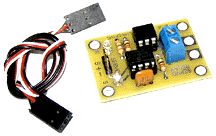
R/C-PWM to Analog Converter Module

This servo-analog converter board provides a two channel capability of converting standard R/C servo PWM pulses to 0-10 Vdc and/or 0-5 Vdc outputs suitable for driving standard lighting dimmer packs or any device that requires a 0-5 and/or 0-10 Vdc variable controlled analog signal input.

Specifications:
Servo input pin headers from R/C unit.
2 - Channel Analog 0-5 and/or 0-10 Vdc DC output is available from the 4 way terminal block for wire connection.
No external power supply is required, the module takes it's supply from the incoming servo drive connections.
Servo inputs: 1 to 2msec pulses.
1-msecs servo pulse gives 0 V DC output.
2-msecs servo pulse gives 5 and/or10 V DC output.
0-5 and/or 0-10 Vdc DC Analog outputs in 80mV increments.
125 steps between 0-5 and/or 0-10 Vdc available.
Maximum drive current -10mA.
Small Board Size: 3-5/8" L x 1-1/4" W x 3/4" H

  Product Description
Catalog No.  Price US $
R/C Servo to Analog Converter Module PWC-2202 $ 85.00
Wizard / Puppet Controllers      

To Top of Page,,,,

 UAV Power Safety Switch Module Hardware Description

IMAGES


Small Board Size:
-" L x -" W x -" H


Instructions

UAV Power Safety Switch Module

This unique module provides a quick and accurate method to remove power between the battery and the UAV flight motors, preventing the motor / props from becoming un-safe in an uncontrolled start up event.

  Product Description
Catalog No.  Price US $
UAV Power Safety Switch Module PSS-3211 $ N/A

To Top of Page,,,,

Small R/C - 1 Ch Switch Board
2 Amp Solid State Relay
Hardware Description


Small Board Size:
1-3/8" L x 1-1/4" W x 7/8" H

Jumper Wire
M to M 6" long

Small R/C -1 Channel Switch Board
2 Amp Solid State Relay

This PIC micro controlled board will take a RC Servo signal from any standard RC transmitter and receiver or Wizard Servo board and toggle the operation of a 2 amp Solid State DC Relay. When there is no servo signal being input, the relay will be off. When the servo signal is about 1.0mS then the relay will come on and will stay on until the servo signal goes to about 2.0 mS and then the relay will go off.

1.0 mSec +/- = Solid State Relay - ON
1.5 mSec +/- = Solid State Relay - Neutral not ON or OFF
2.0 mSec +/- = Solid State Relay - OFF

There is a green LED to indicate when the SS Relay is active and a red LED to indicate that the board is receiving power from the RC Receiver / Controller.
On board wire terminals for Load and Power supply input to load.
Power supply through SS Relay to load can be from 1-60 Vdc up to 2 Amps
Board comes with 6" Male to Male R/C Connector jumper wire.

(R/C transmnitter, receiver, Wizard servo board, power supply not included)

  Product Description
Catalog No.  Price US $
Small R/C Servo 1 Channel Solid State Relay Board - 2 Amp RCR-0999 $ 55.00
Additional Servo Lead Male to Male Jumper - 6"

SMM-0005

$ 6.00
Custom Order, Please Contact Blue Point Engineering for Details

To Top of Page,,,,

R/C 2 Ch Solid State Relay
Interface Board
Hardware Description

RC Servo Switch

Board Size:
2-1/2" L x 1-3/8" W x 1/2" H


Operation Instructions

R/C Servo 2 Channel Solid State Relay Interface Board
New Enhanced Design

Connect this Microprocessor assisted, solid state digital switch board to you radio control receiver and have the option of manually controlling two relay outputs ON or OFF with your R/C transmitter joystick.

Solid State Relays Rated:
1 - 12 VDC at 1 Amp

SS Relay Switching Time:
Time to turn ON = 5.0 mSec, 20 Vdc load
Time to turn OFF= 0.5 mSec, 20 Vdc load

Board uses PWM Control Signal:
1.0 mSec - 2.0 mSec

  Product Description
Catalog No.  Price US $
R/C Servo 2 Channel Solid State Relay Board RCR-1000 $ 70.00
Hitec Servo Lead Male to Male Jumper - 6"

SMM-0005

$ 6.00
Custom Order, Please Contact Blue Point Engineering for Details

To Top of Page,,,,

R/C Servo Solid State Relay
Interface Board with
Duo Control Options
Hardware Description


RC Servo Switch
Board Size:
2-5/8" L x 1-3/4" W x 1/2" H

Operation Instructions


Solid State Relays Rated:
1 - 12 VDC at 1.5 Amp

SS Relay Switching Time:
Time to turn ON = 5.0 mSec,
Time to turn OFF= 0.5 mSec


Board uses PWM Control Signal:
1.0 mSec - 2.0 mSec

R/C Servo 2 Channel Solid State Relay Interface Board
with Duo Control Options
New Lower Pricing

This board allows the activation of two Solid State 2-Amp Relays by using the standard R/C Transmitter joystick. It has 4 modes of operation that are selected by the placement of 2 jumpers. The board is powered by the +5V coming from the servo connector.

Mode 1: Pulse Mode
When the joystick is moved to the left, Relay 1 activates and stays activated as long as the joystick stays in the left position. When the joystick returns to the center position, the relay deactivates. When the joystick is moved to the right, Relay 2 is activated and stays activated as long as the joystick stays in the right position. When the joystick returns to the center position, the relay deactivates.

Mode 2: Toggle Mode
When the joystick is moved to the left, Relay 1 is activated (toggled on) and stays on even when the joystick is returned to the center position. The relay is deactivated (toggled off) by moving the joystick to the left a second time. When the joystick is moved to the right, Relay 2 is activated (toggled on) and stays on even when the joystick is returned to the center position. The relay is deactivated (toggled off) by moving the joystick to the right a second time.

Mode 3: Double Pulse Mode
When the joystick is moved to either the right or left, both relays are activated at the same time and stay activated as long as the joystick is in the left or right position. As soon as the joystick returns to the center position, both relays are deactivated.

Mode 4: Double Toggle Mode
When the joystick is moved to either the right or left, both relays are toggled on and remain on when the joystick is returned to the center position. When the joystick is moved to either the right or left position a second time, both relays are toggled off.

  Product Description
Catalog No.  Price US $
R/C 2 Ch SS Relay with Duo Control Board RCR-2000 $ 85.00
Hitec Servo Lead Male to Male Jumper - 6"

SMM-0005

$ 6.00

To Top of Page,,,,

R/C - 1 Ch Switch Board
10 Amp Solid State Relay
Hardware Description


RC relay

Board Size:
2-1/2" L x 2-1/8" W x 1" H

Solid State Relay Used
Crydom CMX60D10

R/C -1 Channel Switch Board
10 Amp Solid State Relay

This board will take a RC Servo signal from any standard RC transmitter and receiver or Wizard Servo board and toggle the operation of a10 amp Solid State DC Relay. When there is no servo signal being input, the relay will be off. When the servo signal is about 1 mS then the relay will come on and will stay on until the servo signal goes to about 2 mS and then the relay will go off. The relay will then stay off until the servo signal goes back to about 1 mS.

1.0 mSec +/- = Solid State Relay - ON
1.5 mSec +/- = Solid State Relay - Neutral not ON or OFF
2.0 mSec +/- = Solid State Relay - OFF

There is a red LED that will indicate that power is attached to the Power Input terminal block, a red LED to indicate when the SS Relay is active and a green LED to indicate that the board is receiving power from the RC Controller.
On board wire terminals for Load and Power supply input to load.
Power supply through SS Relay to load can be from 1-30 Vdc up to 10 Amps
R/C Servo Connection provides power to SS Relay Controller
Power to Load / Device connected to SS relay not included.

(R/C transmnitter, receiver, Wizard servo board, power supply not included)

  Product Description
Catalog No.  Price US $
R/C Servo 1 Channel Solid State Relay Board - 10 Amp RCR-1996 $ 90.00
Hitec Servo Lead Male to Male Jumper - 6"

SMM-0005

$ 6.00
Custom Order, Please Contact Blue Point Engineering for Details

To Top of Page,,,,

Linear Actuator / DC Motor
Controller by R/C Interface
Hardware Description


Board Size:
3-7/8" L x 2-5/8" W x 3/4" H

Operating Instructions

R/C Interface for Linear Actuator / DC Motor Control
New Design

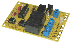
This unique board was designed to allow the directional control of a Linear Actuator (IN / OUT) or DC Motor Rotation (CW / CCW) by using a R/C servo output channel (PWM Signal) to control the DC Motor movements / positions.

Two modes of operation are provided and are selected by the on board Mode Jumper. Toggle On and Off and Latching On and Off Control. On board limit switch inputs stop actuator if positions are exceeded.

The board is powered by the R/C servo connection, but separate power of 12 Vdc @ 5+ Amps must be provided for the linear actuator or DC motor. A power jack or wire terminal is on-board for easy connection to linear actuator motor power. A wire terminal block is also on-board for quick connection to the linear actuator motor wires
There are 2 on-board 6-Amp mechanical relays that work in conjunction to reverse the polarity of the power being supplied to the linear actuator motor that is attached at the motor connection terminal block by PWM (Radio Control) signals.

The board takes standard R/C servo inputs.
The linear actuator controller can also be connected to any of the Wizard Boards or Puppet Controllers for a fully programmable Linear Actuator Controller.

Controller has on-board PIC Microprocessor for R/C to Relay Control. 3-Pin header for quick servo wire connection from R/C receiver or Wizard board.
Tri-Color LED for Motor Rotation / Linear Position Status.

( Linear Actuator, Power supply - R/C System, Wizard Boards Not included )

  Product Description
Catalog No.  Price US $
R/C Linear Actuator Mechanical Relay Module - 6 Amp RCR-8600 $ 195.00
DC Linear Actuators- Assorted Sizes

LAM-0010

-
Programmable Wizard Boards

 -

 -
Custom Order, Please Contact Blue Point Engineering for Details

To Top of Page,,,,

R/C Single Servo Duo Source
Switching Board
Hardware Description


Board Size:
2" L x 1-5/8" W x 1/2" H
Application Setup Overview

R/C Single Servo Duo Source Switching Board

This board allows the control of a single servo by two different sources. One source can be from a hard-wired controller (like a Wizard -12 Board) and the other source can be from a R/C receiver. There is a switch on the board that when switched to the "W" position will lock out the R/C source. The servo attached to the board at the SO header will only respond to the Wizard board attached to the MSI header.
When the switch is switched to the "RW" position, control can be from either the Wizard board or the R/C receiver. In the RW mode, a second input from the R/C receiver attached to the RI-2 header will determine which input (either from the Wizard board attached to the MSI header or from the R/C servo input attached to the RI-1 header) will be used to control the servo attached to the SO header.
The board has a terminal block to allow the remote placement of a R/C Lockout switch.
Power to the board is provided by the connections to the R/C receiver and the Wizard board.
(Servo, Wizard Board, R/C Transmitter-Receiver, Servo Leads not included)

  Product Description
Catalog No.  Price US $
R/C Single Servo Duo Source Switching Board RCS-5025 $ 95.00
Hitec Servo Lead Male to Male Jumper - 6"

SMM-0005

$ 6.00
Custom Order, Please Contact Blue Point Engineering for Details

To Top of Page,,,,

R/C Controlled Duo SS Relays and Variable DC Voltage Output
Interface Board
Hardware Description


-


Board Size:
4-1/2" L x 3" W x 1/2" H

Solid State Relays Rated:
1 - 12 VDC at 1.5 Amp

SS Relay Switching Time:
Time to turn ON = 5.0 mSec,
Time to turn OFF= 0.5 mSec


DC Output 0-5, or 0-10 at 80mA

Board uses PWM Control Signal:
1.0 mSec - 2.0 mSec

Board requires
12VDC @ 500mA Power Supply
3- Channel R/C Servo outputs (PWM)


Operation Instructions

R/C Controlled Duo Solid State Relays and
Variable DC Voltage Output Interface Board

This board was designed to take input from 3 separate R/C servo signals and generate a 0-10 or 0-5VDC output (up to 80 mA) and control 2 sets of 2 Solid State Relays On and Off.
For the voltage output part of the board, the output range is selected by placing or removing a shorting block on the Voltage Output Select Jumper header pin. If it is in place, the output for that channel will be 0-5V. If it is removed, the output for that channel will be 0 ­ 10V.
For the SSR part of the board, each set of 2 SSRs will operate in 1 of 4 modes which is selected by the placement of shorting blocks on the 2 header for each set. Each set will operate independently from the other. SSRs 1 and 2 are grouped together and will respond to the servo input coming from Servo Input Header #2. SSRs 3 and 4 are grouped together and will respond to the servo input coming from Servo Input Header #3. Each set will have 4 operation modes. The Relay modes are as follows:

Mode 1: Pulse Mode
This mode is selected by removing both jumpers. When the joystick is moved to the left, Relay 1 activates and stays activated as long as the joystick stays in the left position. When the joystick returns to the center position, the relay deactivates. When the joystick is moved to the right, Relay 2 is activated and stays activated as long as the joystick stays in the right position. When the joystick returns to the center position, the relay deactivates.

Mode 2: Toggle Mode
This mode is selected by placing the jumper on J1. When the joystick is moved to the left, Relay 1 is activated (toggled on) and stays on even when the joystick is returned to the center position. The relay is deactivated (toggled off) by moving the joystick to the left a second time. When the joystick is moved to the right, Relay 2 is activated (toggled on) and stays on even when the joystick is returned to the center position. The relay is deactivated (toggled off) by moving the joystick to the right a second time.

Mode 3: Double Pulse Mode
This mode is selected by placing the jumper on J2 and removing the jumper from J1. In this mode, when the joystick is moved to either the right or left, both relays are activated at the same time and stay activated as long as the joystick is in the left or right position. As soon as the joystick returns to the center position, both relays are deactivated.

Mode 4: Double Toggle Mode
This mode is selected by placing jumpers on both J1 and J2. When the joystick is moved to either the right or left, both relays are toggled on and remain on when the joystick is returned to the center position. When the joystick is moved to either the right or left position a second time, both relays are toggled off.

(Board Power Supply, RC Transmitter / Receiver not included)

  Product Description
Catalog No.  Price US $
R/C Duo SS Relays / DC Voltage Output Interface Board RVR-3025 $ 235.00
Hitec Servo Lead Male to Male Jumper - 6"

SMM-0005

$ 6.00

To Top of Page


Blue Line

RF / REMOTE

To Top of Page,,,,

Wireless RF 4 Ch
R/C Servo Controller
Hardware Description.....

RF Servo Controller

Wireless RF 4 Ch R/C Servo Controller

Wireless 4 Channel R/C Servo Controller.
Using the handheld RF Transmitter, you can control 1-4 R/C servos and there movements.

RF 4 Ch Transmitter
RF 4 Ch Receiver board
RF/ Servo Switch Board
4-Ch Servo Driver Board

( Power Supply, R/C Servos, not included )

Setup Overview

  Product Description
  Catalog No.  Price US $
4-Channel R/C Servo Controller (315 MHz)
( 315 MHz standard, 418, 433 MHz additional fees )
RRC - 6313 $ 655.00
Custom Order, Please Contact Blue Point Engineering for Details

To Top of Page,,,,

Wireless RF 1 Ch
Servo Controller
Hardware Description.....


Remote Servo

Instruction Manual


-

Wireless RF 1-Ch R/C Servo Controller

RF Wireless 1-Channel R/C Servo Controller.
Using the handheld RF Transmitter, you can easily control 1-R/C servo and it's movements from user programmed position A to position B travel.
Servo travel limits can be user programmed into controller board for precise servo movements needed when activated.

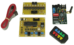
RF Channel Switch and 1-Ch Servo Driver Board can be pre-set by on board selection switches to operate from any one of the RF hand held transmitter channel buttons 1-8, allowing you to choose a specific channel for the servo operation, leaving the other channel buttons open to control more optional attached devices as needed. A single pass through connector makes connecting other optional RF devices to the Wireless1-Channel R/C Servo Controller and master RF Receiver board easy to do. Using an optional cable add-on adapters you can also connect up to 8 different optional devices to the main RF receiver. (Motor Driver , LED, Lighting boards Sound Playback boards, Special Effects boards, etc) controlling all of them from one RF hand held transmitter and buttons 1-8.Board also have multiple power connection wire terminal blocks, so a single power source can power RF receiver, and RF Channel Switch, 1-Ch Servo Driver Board from a single supply.

RF 8-Ch Long Range Transmitter (315 MHz)
RF 8-Ch Receiver board (315 MHz)
RF Channel Switch and 1-Ch programmable Servo Driver Board / Connection Ribbon Cable

( Power Supply, R/C Servos, not included )


Setup Overview

  Product Description
  Catalog No.  Price US $
1-Channel R/C Servo Mouth Controller (315 MHz) PMC - 2344 $ 495.00
Custom Order, Please Contact Blue Point Engineering for Details

To Top of Page,,,,

RF 8-Ch M8/T4 Receiver Module Hardware Description.....


RF Transmitter 8-CH
RF Receiver Board Size:
3-1/2" Long x 2-3/8" Wide

8-Ah Ribbon Connector
4-Ah on-board output blocks
Channel outputs TTL 1-8 +/- 0/4VDC Drive

* NOTE: Handheld RF Transmitter
not included.

OPTIONAL ADD-ON BOARDS
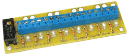
RF Receiver
Optional Adapter -8Ch
Wire Terminal Block and LED Status Board
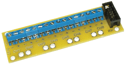
RF Receiver
Optional Adapter -8Ch
Wire Terminal Block Board

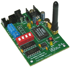
Professional 8/4 Channel RF Receiver Module

FCC Part 15 Compliant RF System
8/4 Channel Remote Control - Receiver
Manufactured in the USA

Type:
RF Radio (315,418,433 MHz) 1-4 Channels and 1-8 Channels (FCC Part 15 Compliant Components).
Additional Frequencies Available ,418,433 MHz - extra fees
Operating Voltage: 9-12 VDC @ 1 Amp (Wall Power Supply Adapter, 1Amp Battery Supply).
Antenna: Adjustable Angle, Receiver Antenna 418 MHz (2" long).
Control Output Mode: Momentary-8CH / Toggle-4CH, on-board DIP Switch user selection set.
LED Channel Status: Ch1-4 LED's On/Off, MODE Indicator- Receiver Activity, Learn mode.
Switched Output Application: -4 VDC switched output voltage at 200 mAmp per channel. Channels 1-8 -5VDC, On-board Connector for +5VDC circuit return.
BOARD: wire terminal connections, LEDs on receiver board for CH1-4, Ribbon connector for Ah 1-8 out.
2.5 x 5mm Power jack for power connection. ON-OFF Power Switch, LED Status Lights. 5VDC Regulator for stable operation and various board power supply options. Commercial Grade 3 Layer PCB, with small board footprint size. (3-1/2" L x 2-3/8" W x 1/2" H electronics, 2" long antenna, 3 mounting holes)
Optional Add-On / AUX Support Boards: Quick connection to optional add-on application boards
Switched On-Board Outputs: On-board wire terminal block for direct application connection to board channels 1-4 outputs. (no optional add-on board required)
LEARN Mode: On-Board button switch, auto code-binding to Transmitter, Status LED.
System Requirements: Power Supply, RF Transmitter, Application Device / Load
Optional AUX Boards: Relays, Audio Playback, DC Motor Control, Servo Control, Lighting FX, more.
SET-UP: Quick connections, on board setting for easy use and user setup operations.

* NOTE: Handheld Transmitter not included, a transmitter type must be selected to use this Module. Receiver outputs TTL +/- 1-4VDC at 200 mA on Ah 1-8 when activated.

( Power supply for Receiver not included )

Setup Overview

Instructions Document

.Optional Application Board Listing

  Product Description
Catalog No.  Price US $
RF 8-Ch M8/T4 Receiver Module ( NO TRANSMITTER)
Available in: 315 - standard
418, 433 MHz Range - additional fees

WRX - 0080

$ 295.00
Optional 8-Ch Adapter Wire Block / LED's on 12" cable

REC - 0201

$ 70.00
Optional 8-Ch Adapter Wire Block on 12" cable

REC - 0206

$ 47.00
* Long Range Handheld Transmitter

LRT - 0100

$ 70.00
* Compact Handheld Transmitter

CRT - 0050

$ 75.00
Optional 8-Ch AUX boards  

 Call BPE
Optional - Custom Receiver Box and Lid cover

 BOX - 0045

$ 45.00

To Top of Page,,,,

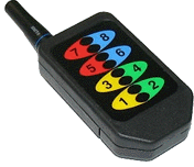
RF Transmitters Hardware Description.....


Long Range-(Antenna)
Handheld Transmitters

RF Transmitter

FCC Part 15 Compliant RF System
1-8 Channel Remote Control - Transmitter
Manufactured in the USA

315 MHz - Standard

Hand Held Transmitter:
Type: RF radio(315 MHz)

1- 8 Channel Soft Button

Long Range Handheld Transmitter (1000' Range)
(External rubber 418MHz antenna)
8-Channel Keypad with plastic overlay


Instructions Document

  Product Description
Catalog No.  Price US $
Long Range Handheld Transmitter (a) 315 MHz

LRT - 0100

$75.00


To Top of Page

Blue Line

LIGHTING / FX

To Top of Page,,,,

R/C LED Strobe and
All ON/OFF FX Controller
Item Description


Board Size:
2-1/4" L x 2" W x 1/2" H

LED Output 12VDC @ 2 Amp

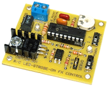
R/C LED Strobe and ON/OFF FX Controller

This board allows the activation of a 12 VDC LED strip in a Constant On or in a Strobing Effect mode by using a standard R/C joystick.

When the joystick on the R/C transmitter is moved to the left, LED Light is toggled on and off and when the joystick is moved to the right Light Effect Strobing is toggled on and off

It has 2 modes of operation that are selected by the Mode Select Switch. The board is powered by the +5V coming from the R/C receiver Signal Input. The LED strip is powered via the 2.1mm barrel power connector or the adjacent terminal block. There is a red LED indicator on the board that will provide on/off status of the attached LED strip. When the board is operated in the Strobe Mode, there is a pot on the board that will control the rate of strobing.

(VDC power supply, R/C Receiver / Transmitter ,LED's not included)

  Product Description
  Catalog No.  Price US $
R/C LED Strobe and On/Off FX Controller RLF-3505 $ 75.00
LED Light Strips        

To Top of Page,,,,

  R/C Controlled Navigation
Lighting Board
Item Description

LED Output 12VDC
2 Amp per channel

Board Size:
2-1/4" L x 2" W x 1" H
1-Ch controls all Three Group Effects

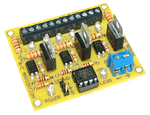
R/C Controlled Navigation Lighting Board
(DRONE, UAV, Robot, Airplane)

This board was designed to allow the control of 3 groups or channels of LED's or LED strips as Navigation Lighting by using the control (PWM) signal from a R/C system Receiver and Remote Transmitter.

Group One: Red, (Starboard), Green (Port) and White LEDs / Strips.
Group Two: Red. White Flashing (Beacon) LED's or Strips.
Group Three: White (Landing) LED's or Strips.
Note: Any color LED's or strips can be connected, powered and controlled from this boards. 2 Amps per channel at 12 VDC output. On board LED status lights.

Operation:
When the joystick on the R/C transmitter is moved to the left, Light Effect Group one and two is toggled on and off and when the joystick is moved to the right Light Effect Group three is toggled on and off The signal input is attached at the R/C Signal Input 3-pin Header from the R/C receiver. The board is powered by the 5VDC supplied by the R/C Input receiver and is indicated by a yellow Board Power LED. Power for the LED strips is attached (9-12 VDC) at the Output Power Connection terminal block as is indicated by the red Output Power LED.
(VDC power supply, R/C Receiver / Transmitter ,LED's not included)

  Product Description
  Catalog No.  Price US $
R/C Controlled Navigation Lighting Board RLF-3520 $90.00
LED Light Strips    

To Top of Page,,,,

R/C LED 10-Effects Board Hardware Description


--


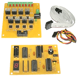
Radio Controller Receiver LED 10-Effects Board

The control board is designed to allow the manual selection of 10 different effect modes and the activation ON/OFF of 8-LED Strip Channels to playback the selected Effects by remote R/C Transmitter using servo (PWM) output signals. There are 2 boards to this project ­ a Main Board and a Remote board This board allows the manual activation fof10 different light effect modes for 8-channels of 12 VDC LED strips using servo CH-1 of an R/C Transmitter joystick movement (Left) to toggle, select the effects mode 0-9, then joystick movement (Right) to activate the LED Strips ON / OFF with the effect mode selected. The board is powered by the +5V coming from the servo connectors and the LED strips are connected to their own pass through power supply 12VDC.

LEFT Movement Toggle-selection of Effect 0-9
When the R/C Transmitter joystick Ch-1 is moved to the left, the effect mode 0-9 will be selected. Each time the joystick is moved left, an effect number will be selected, moving the joystick center and left several
times will move up the effect mode 0-9, then repeat when 9 is reached. The on board LED Display will show which effect has been selected. Once a number has been selected, the joystick is in center position (Neutral position).

RIGHT Movement - ON / OFF Toggle - LED Strips
When the R/C Transmitter joystick Ch-1 is moved to the right the selected effects mode is activated ON and the remote LED board operates. The joystick is kept in center (Neutral position). When the R/C Transmitter joystick Ch-1 is moved to the right again the selected effects mode is activated OFF and the remote LED board stops.

Effect Modes:
The following modes (10 Effects) are pre-programmed on the Main Board, and selected (toggled) by R/C Transmitter joystick movement left position input. Each mode is shown as a number(0-9) on the LED segment display, when selected.

Mode 0: All LED's ON
LED Strips will be ON for all - 8 channels.
Mode 1: Marquee Effect
LED Strips will cycle from 1 ­ 8 repeatedly at a rate set by the potentiometer.
Mode 2: Cylon Effect
LED Strips will cycle from 1 ­ 8 and then 8 ­ 1 repeatedly at a rate set by the potentiometer.
Mode 3: Knight Rider Effect
LED Strips will cycle in pairs ­ Strips 4&5, 3&6, 2&7 and 1&8, rate determined by the potentiometer.
Mode 4: Strobe Effect
LED Strips will all flash together at a rate determined by the potentiometer.
Mode 5: Random Flash Effect
Each LED Strips will flash ON and OFF randomly at a speed rate determined by the potentiometer
Mode 6: Heart Beat Effect
All LED Strips will quickly flash two times, wait 3 seconds and then repeat.
Mode 7: Flash-Marquee Effect
All LED Strips will flash 4 times then cycle strips from 1 ­ 8 wait 2 seconds, flash all strips 4 times
then cycle strips from 8 ­ 1, wait 2 seconds, then repeat.
Mode 8: FireFly Effect
LED strips 1&2 will flash once, pause for X period, LED strips 3&4 will flash 2 times, wait for X period,
LED strips 5&6 will flash 3 times, wait for X period, and LED strips 7&8 will flash 4 times, wait for X
period, and then repeat. X Period will be determined by the potentiometer
Mode 9: Alternating Rail Road Crossing Light Effect
LED strips 1,2,3&4 will alternate back and forth On/Off with LED Strips 5,6,7&8 On/Off at X rate.
(X rate will be determined by the potentiometer adjustments)

( Radio Control System, R/C Receiver, Power supply, LED's not included )

  Product Description
 Catalog No.  Price US $
 R/C LED 10-Effects Board RFB-5025  $ 395.00
Custom Order, Please Contact Blue Point Engineering for Details

To Top of Page,,,,

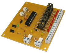
R/C LED Effects Board
200 mAmp Output
Hardware Description

RC lighting

Radio Controller Receiver LED Effects Board

This unique board will allow use of a RC joystick or any wizard board servo output to control eight channels of remote DC lights (LED or incandescent) in 2 different sequences. Each channel is capable of driving up to 200 mA of lighting. An on-board LED for each channel indicates that the channel is active. Two on-board SS relays ­ one for each sequence - will also activate depending on which sequence is selected. A Mode Selection Switch will allow the user to toggle between Momentary On or Toggle On/Off modes. For example, with the Mode switched to Mode 1 (Momentary On), when the RC joystick is tilted to the left, Sequence 1 will start and Relay 1 will activate. Sequence 1 and Relay 1 will continue to be active as long as the joystick stays in the left position. When the joystick is in the center position, neither sequence will be selected. In Mode 2 (Toggle On/Off), when the joystick is tilted to the left and then returned to the center position, Sequence 1 will start and Relay 1 will activate. The sequence will continue and the relay will stay activated as long as the joystick remains in the center position. To stop this sequence, the user must tilt the joystick to the left a second time, toggling the sequence off. The same applies for Sequence 2. There are 2 potentiometers on board, one for each sequence that allows the user to control the rate of each sequence. The board has an on-board On/Off switch. Power to the board is supplied by the 5V line of the RC Servo connection and should have sufficient current to drive the board and all of the eight light channels (~2A max).

Sequence 1 ­ Cylon Effect:
When the Joystick is tilted to the left, Relay 1 actuates and a single channel rasters back and forth. Rate 1 Potentiometers will control the rate of the rastering.

Sequence 2 ­ Strobe:
When the Joystick is tilted to the right, Relay 2 actuates and all channels strobe on and off in unison. Rate 2 Potentiometer will control the rate of the channel strobing.


( Radio Control System, R/C Receiver, Power supply, LED's not included )

  Product Description
 Catalog No.  Price US $
 R/C LED Effects Board RFB-3005  $ 285.00
Custom Order, Please Contact Blue Point Engineering for Details

To Top of Page,,,,
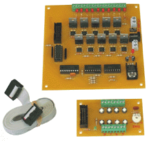
10 Channel LED Controller Board
8 - Effects / Remote Controlled
Hardware Description


Board Size:
4-1/2" L x 3-3/4" W x 1" H


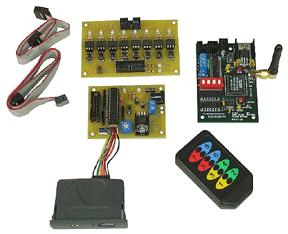
Optional RF Controller
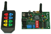
Transmitter and Receiver

RF Transmitter and Receiver Board Set

10-CH LED Effects Controller
with 8 - Remote Selected Effects

This unique controller was designed to control 10 externally connected LEDs, LED Strips or Lights in one of 8 modes (patterns) by Remote Control. For the patterns that have adjustable times, the rate at which the patterns run is set by the Rate Pot located on the Remote Switch Board. Power to the board (Battery) is connected via the 2.1mm barrel connector or via the adjacent 2-position terminal block, Power to the board is turned on and off by either the small power switch or a remote switch attached to the Remote Switch terminal block. There are on-board LEDs that indicate when each channel is active. The modes are selected by manually pressing the appropriate Mode Switch on the Remote Switch Board that is connected to the Main Board via a 6 foot ribbon cable, or this can also be connected to an optional RF Wireless Transmitter and Receiver set, a DMX Wireless Controller, Stage Control Console, or operated by Off Stage Director / Dance Cordinator. Once a mode is selected, it will remain selected even if power is cycled to the board.

Modes:
There are 8 modes available. Note: Other custome routines can be programmed by BPE into this controller. Contact BPE for informatiion.

The current modes are as follows:

Mode 1 ­ All Off
All channels are off.
Mode 2 ­ All On
All channels are on constantly. Note: Do not drive more than 2A max total in this mode.
Mode 3 ­ Strobe
All channels flash on and off continuously at a rate determined by the Rate Pot.
Mode 4 ­ Marquee Right to Left
Channels cycle on and off, one at a time from right to left at a rate determined by the Rate Pot.
Mode 5 ­ Marquee Left to Right
Channels cycle on and off, one at a time from left to right at a rate determined by the Rate Pot.
Mode 6 ­ Cylon
Channels flash from 1 ­ 10 and then 10 to 1, back and forth continuously at a rate determined by the Rate Pot.
Mode 7 ­ Knight Rider Effect
Channels raster 5 ­ 1 and 6 ­ 10 repeatedly at a rate determined by the Rate Pot.
Mode 8 ­ Random Flash
Channels 1 ­ 10 randomly flash at a rate determined by the Rate Pot.

Board requires 12 Vdc @2 Amp Power supply
Each output channel can drive 2 Amps.

( Power supply, LED's not included )

Please contact Blue Point Engineering to discuss other light effects you need programmed into the controller board.

  Product Description
 Catalog No.  Price US $
RF 10-CH LED Effects Controller CLE-3210  $ 995.00
Optional LED Light Bars
Optional LED light Strips

..

..
Custom Order, Please Contact Blue Point Engineering for Details

To Top of Page,,,,

LED Light Strips Hardware Description
strip leds-
LED Strips do not come with Power Wires
connected, Image shown, illustrates typical
power connection that can be easily done.
Optional Quick Connectors available.
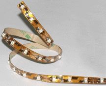

strip leds
The LED strips are very flexible


strip leds
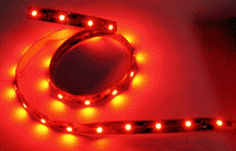
Red LED Strip shown

Photo not color correct
actual LED's all bright Red

LED Light Strips


These universal 19 Inch Flex-LED Surface Mounted Light Strips are excellent for use in projects requiring lighting or for use when special effect lighting is need and connected to an FX controller.

The LED strips are very flexible and can be wrapped or attached to almost any surface and shape. Each strip comes with an Adhesive back so they can mount just about anywhere.

The standard colors have an LED spaced 5/8" apart, 30 LED's Per Strip. Strips are 1/4" Wide x 19" Long, or when cut to the smaller length ( 3 LED's ) is 2" long x 1/4" wide.

Strips are easily cut to different sizes with cut markings shown on the tape so that you always get the proper LED's to resistor ratio needed.
Smallest size that can be cut is A 3 LED strip. When properly cut each strip also contains a solder pad for the connection of the positive and negative power wires.

Each strip operates from 12vdc @170mA per 19" length.

Note: The minimum bending radius is 2 cm. The strip may be bent over a smaller radius of the circuit board containing no electronic components and such bends should be made once and fixed in position to avoid cyclic fatigue.

Lumen Output :
White = 600 at 12vdc @170mA
Blue = 300 at 12vdc @170mA
Green = 500 at 12vdc @170mA
Red = 500 at 12vdc @170mA
Yellow = 450 at 12vdc @170mA


( 12 VDC Power Supply , power connection wires and controller not included. Stripes do not have power wires connected, some sldering required to attach wires. )

NOTE: LED Strips do not come with Power Wires connected.

  Product Description
Catalog No.  Price US $
LED Light Strips - 19" Long x 1/4" wide (30 LED's per strip)
LED Color - Red
LED Color - Green
LED Color - White
LED Color - Blue
LED Color - Yellow
LSL-0130
LSL-0131
LSL-0132
LSL-0133
LSL-0134
$ 13.95
$ 14.95
$ 16.95
$ 14.80
$ 14.80
Custom ordered, please allow 2 to 3 weeks for delivery


To Top of Page

To Top of Page,,,,


Blue Line

AUDIO / VIDEO

To Top of Page,,,,

Wireless RF 8 Ch Audio
MP3 Playback Controller
Hardware Description
Wireless MP3 Controller

Wireless RF 8 CH Audio MP3 Playback Controller

Wireless 8 Channel MP3 Audio Playback controller
Using the handheld RF Transmitter, any of 1-8 channels of MP3 Audio can be selected for playback form the 8 Channel MP3 playback board.

There are 3 modes of operation provided ­ Sequential, Random (10 Channels Available) and Individual Channels 1-8 selection for playback.

MP3 Player
An MP3 Stereo Audio Controller, that when triggered by RF remote switch input board will cause the player to play back 1 to 8 MP3 files that are stored on a USB flash device (USB flash drive not included). These MP3 files can be of any size up to the capacity of the USB flash device. You can have any number of files up to 8 on the flash device. Board operates from 9 VDC @ 0.5 Amp Power Supply.
1/8" miniplug audio output jack.

(Power Supply, Sound Source, USB drive, Audio Cable, Audio Amp, and Speakers not included)

  Product Description
  Catalog No.  Price US $
8-Channel RF Audio-Stereo Sound Switch RFA-0689 $ 695.00
Custom Order, Please Contact Blue Point Engineering for Details

To Top of Page,,,,

R/C Servo Controlled
4-Ch Video Switcher
Hardware Description


Small board approx.
2" x 4" ( 107mm x 69mm)

5 - BNC video connectors,
9Vdc power supply socket

LED Status lights and
PWM servo connector

Information Document

Servo Controlled 4 - Ch Video Switcher

Unique servo signal controlled electronic video switching system which provides clean and fast switching between 4 video channels to 1 channel.
System allows 4 video channels to be switched to 1 master channel, by adjusting the R/C transmitter joystick, or assigning a servo signal value from any R/C PWM signal controller.

The Video switcher board will switch one of four video input signals to a buffered video output line. The Video Switcher board is suitable for all standard CCTV type video signals.

Small board approx. 2"x 4" with BNC connectors for the video and 9Vdc supply socket and servo connector.
Video Switching is done by a solid state unit using a standard 4 to 1 mux under micro processor control. The processor also measure the incoming servo pulse and determine which input to connect to the video output.

System is excellent for operating 4 different cameras, and sending video signal from one of the 4 cameras out to a remote transmitter. Put full 360 degree vision on your robot, airplane, animatronic character, or setup a covert operation with remote control.

Servo Signal
Adjusting the input signal (ie the pulse duration) will alter the video input being fed to the video output. The led by the side of the input socket will light when that particular input is live.
Input 1 is for pulse widths between 1.0 -1.25 msecs
Input 2 is for pulse widths between 1.25 -1.5 msecs
Input 3 is for pulse widths between 1.5 -1.75 msecs
Input 4 is for pulse widths between 1.75 - 2.0 msecs.
Power needed: 9VDC at 250mA - 2.1, power socket-center positive

R/C receiver, Video Transmitter, Cameras and
9 Vdc power supply not included

  Product Description
  Catalog No. Price US $
 Servo Controlled 4 - Ch Video Switcher SVS-0550 $ 250.00
 Servo Controlled 4 - Ch Video Switcher -NO BNC connectors

SVS-0555

$ 240.00
     

To Top of Page

To Top of Page,,,,

Blue Line

GAMES / ACTIVITIES

To Top of Page,,,,

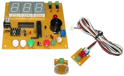
LASER Target GAME System Item Description

Main Board Size:
4-7/8" L x 3-3/8" W x 1" H

Remote LED Board Size: (not shown)
1-71/4" L x 3-3/8" W x 7/8" H

CDS Cell Sensor Board:
1-1/8" L x 1" W x 7/8" H

LASER Caution Note

LASER Target GAME System

This project will detect "hits" from a LASER beam on a remotely mounted target board and display the hit count on a large LED display. When hits are detected, the display will count down or up and trigger a beeper, 2 large LEDs (one located on the Main Board and the other located on the remote board) and SSR #1 for 3 seconds. When the hit count gets to 0 the large LEDs will rapidly flash, the beeper will annunciate continuously and SSR #2 will actuate. This will continue until the reset button is pressed (a remote terminal is available), or if the Auto/Manual switch is set to Auto, the board will automatically reset after a user-defined time interval. The user can set the hit count starting value (1 ­ 100) and the reset time (1-20 seconds) . The target boards are attached by a 6 foot ribbon cable. The target sensitivity can be adjusted by an on-board potentiometer to allow optimum response in different lighting conditions. The beeper can be silenced with an adjacent slide switch.
Both Count UP and Count down options are on-board

Main Board is powered by 12 Vdc 900mA power supply

(Power supply, LASER, not included)

LASER Caution Note

  Product Description
  Catalog No.  Price US $
LASER Target GAME System LTG-0522 $385.00
Custom Order, Please Contact Blue Point Engineering for Details

To Top of Page,,,,

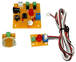
LASER Target Relay Item Description

Main Board Size:
2-1/4" L x 2-1/4" W x 7/8" H

Remote LED Board Size: (not shown)
1-71/4" L x 3-3/8" W x 7/8" H

CDS Cell Sensor Board:
1-1/8" L x 1" W x 7/8" H

LASER Caution Note

LASER Target Relay

This board will detect "hits" from a LASER on a remotely mounted target. When hits are detected, 2 large LEDs (one located on the Main Board and the other located on the remote sensor board) and both SSRs will be activated ON for 3 seconds. The target board is attached by a 6 foot ribbon cable. The target sensitivity can be adjusted by an on-board potentiometer to allow optimum response in different lighting conditions. Board wil automatically reset waiting for next LASER hit.

Main Board is powered by 12 Vdc 900mA power supply

(Power supply, LASER, not included)


LASER Caution Note

  Product Description
  Catalog No.  Price US $
LASER Target Relay LTG-0320 $85.00
Custom Order, Please Contact Blue Point Engineering for Details

To Top of Page


To Top of Page,,,,

Blue Line


MECHANICAL

Red Dot Icon . Mechanical Devices / Systems / Kits - Product Listing
Ground Station Tracking System R/C Servo Control Fluid Pump
R/C Servo Control Air Pump Rescue POD Drop Mechanism
Tennis Ball Drop Mechanism Sensor POD Drop System
Ping Pong Ball Drop Mechanism Hexacopter Winch System
Duo LASER R/C Tracking Mechanism  Video Drop POD System
Camera Pan and Tilt Mechanism R/C Servo Pneumatic Valve
R/C Servo Universal Drop Mechanism  

Mini Fluid Pump Hardware Description


Pump Instructions

servo pump

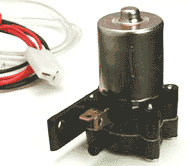
Mini Fluid Pump

Small 12 Volt DC powered pump for moving fluids.

12 Vdc operated electric pump
16 psi Water Pressure
135 ml per minute pumping action
2.1 amp operating current
3.5 amp motor start amp
Self-priming electric pump
Pump Mounting Bracket

Pump comes with connection tubing, electrical hook up wire, tube adapter, plastic tube "T"


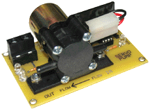
Servo Controlled Pump - Switched On/ Off Board
Connect the Servo Controlled Switch Board to your R/C receiver or any Wizard Board Servo output and have the option of switching ON and OFF the mini fluid pump. Board will switch 12Vdc directly through on-board Power connercter wire terminal to the Solid State Relay and over to the Pump Motor.
Control board electronics is powered directly from R/C receiver or servo output, with quick connector and wire terminal block for easy set-up and control.

Power supply not included.

  Product Description
Catalog No.  Price US $
Mini Fluid Pump LFP-0913 $ 35.25
Mini Fluid Pump with Optional R/C Servo Controller

MWC-0344

$ 85.00

To Top of Page,,,,

R/C Servo Controlled
Tennis Ball Drop Mechanism
Product Information

IMAGES

.......R/C Servo Controlled Tennis Ball Drop Mechanism

Unique R/C servo operated -

  Product Description
Catalog No  Price US $
 R/C Servo Tennis Ball Drop Mechanism TBD-2901  $ N/A
OUT OF STOCK
Custom Order, Please Contact Blue Point Engineering for Details

To Top of Page,,,,

R/C Servo Controlled
Ping Pong Ball Drop Mechanism
Product Information

IMAGES

.......R/C Servo Controlled Tennis Ball Drop Mechanism

Unique R/C servo operated -

  Product Description
Catalog No  Price US $
 R/C Servo Ping Pong Ball Drop Mechanism PBD-2305  $ N/A
OUT OF STOCK
Custom Order, Please Contact Blue Point Engineering for Details

To Top of Page,,,,

R/C Servo Controlled
Universal Drop Mechanism
Product Information

IMAGES

.......R/C Servo Controlled Universal Drop Mechanism

Unique R/C servo operated mechanism designed to hold payload on UAV and drop it under command from a servo and remote RF transmitter signal

Module is constructed from machined aluminum with attached pull pin setup assembly attached to servo arm.. When R/C servomotor is activated will pull back release pin holding payload. Mounting holes on drop mechanism makes mounting easy.
Heavy duty servo is pre-attached to drop module. (rerquires servo control board not included to operate and RF Receiver and Transmitter Modules)

(Servo control board and RF Receiver, Transmitter, power supply not included)

  Product Description
Catalog No  Price US $
R/C Servo Controlled Universal Drop Mechanism DDM-2533  $ 85.00
RF R/C Servo Control Board    
 Payload Modules    
Custom Order, Please Contact Blue Point Engineering for Details

To Top of Page,,,,

R/C Servo Controlled
Winch System
Product Information
IMAGES

.......R/C Servo Controlled Winch System

Unique R/C servo operated -

  Product Description
Catalog No  Price US $
 R/C Servo Winch System SCW-2355  $ N/A
OUT OF STOCK
Custom Order, Please Contact Blue Point Engineering for Details

To Top of Page,,,,

Blue Line

To Top of Page

Copyright © 2016 Blue Point Engineering Inc., All Rights Reserved


Robert Van Deest - Professional UAV, Robot Designer and Builder
Ryan Van Deest - Professional UAV, Robot Designer and Builder