Welcome ...Product Categories ...What's New ...Sale Items ...Communications
E-Mail ...How to Order ...Order Form ...Catalog ...Legal Notices
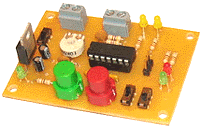
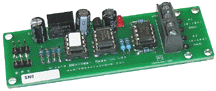
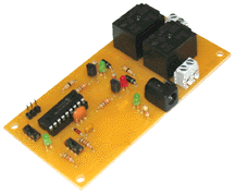
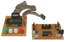
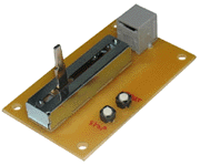
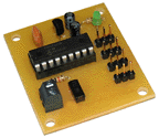
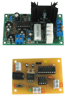
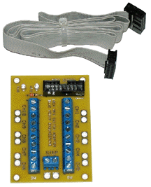
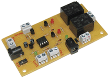
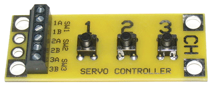
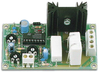
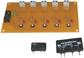
| 3-Switch
(Servo) Controller 3 Programmable Servo Movements |
3
Program Servo Control Board 3 Routines to 1 Servo / Relay Output |
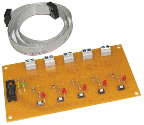
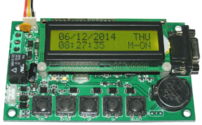
Electronic
Clock /Timer Multiple Triggers Day, Week |
| Programmable
AC Dimmer AC Lighting Dimmer, User program |
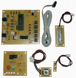
Ventriloquist
Puppet Controller Program 5-Ch Remote- Servo / Relay Board |
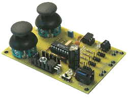
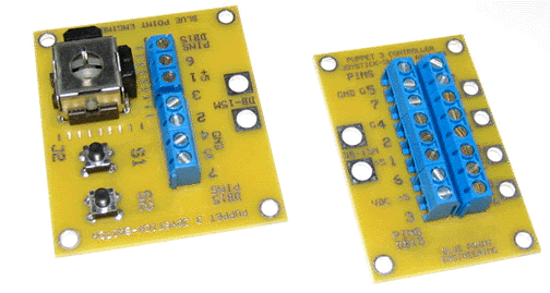
Puppeteer
- 3 Joystick Board. 2 - Servo / Digital / Joystick / Auto |
| 12Vdc
Input Servo Controller Servo Position by 12 VDC Signal |
Mini
Servo Checker Servo Tester / Special Features |
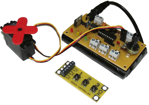
4-Ch
Servo Record / Play System Joystick 4Ch Servo Record / Playback |
| 0-10
Vdc HC Program Controller 0-10 Volt High Current Analog Control |
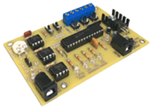
Random
6-Ch Servo Controller Programmable 6Ch Servo / FX Features |
4
Ch Manual Servo Control Joystick Controlled 4 Servo / SS Relay |
| 0-10
Vdc Output Controller 0-10 Volts programmable output |
Programmable
Random Board Programmable Output / Features / FX |
Wizard
- 6 Control Board 2Ch Random Servo / 1Ch Pulse Servo |
| 0-10
V Input Servo Control 0-10 Volt Servo Motion Control |
Random
8-Ch SS Relay Controller Programmable 8Ch Relay / FX Features |
Costume
Servo Controller 1 - Servo Ch - Switch / Automated |
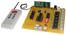
| RF
Puppet / Wizard Interface Puppet - Wizard Tran / Rec Control |
RF
Wizard Board Controller Wizard - Board.Tran / Rec Control |
Joystick
Servo - Relay Control Manual 4Ch Servo - 1Ch Relay Board |
| Micro
Cam Pan and Tilt Controller Manual 2Ch Servo-1Ch Relay Servo Control |
Remote
Pan and Tilt Controller Remote/Manual 2Ch Servo-1Ch Relay Servo |
R/C Motor
Relay Controller DC Motor Control by R/C Servo Ch |
| Solenoid / Air Valve
Driver Air/Water Valve Control with FX |
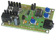
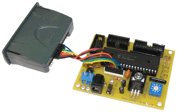
AutoTalk Controller Sound to Servo Motion |
Joystick / Program
Servo-Relay Programmable 4Ch Servo & 1Ch Relay |
| Remote Programmable
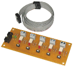
4-Ch Relays Programmable Solid State Relays 10Amp |
Programmable 1-Ch
Relay 3 Amp Programmable Solid State Relay 3Amp |
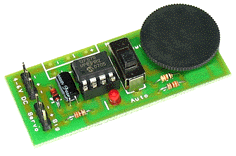
Ultrasonic Servo Tracker 1 Servo 3 Sensor Motion Control |
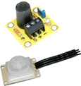
| Programmable PIR Sensor
Relay Programmable Solid State Relay 2Amp |
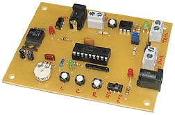
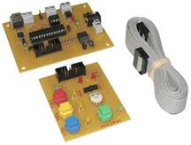
Manual Puppeteer
Controller 4Ch Servo Switch/Potentiometer Inputs |
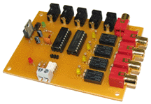
R/C Video Switcher
A Servo Control 4Ch Video In / 1Ch Out |
| R/C Single Servo Duo
Source Switch 2 servo boards to 1 servo input |
FLEX Sensor Servo
Controller 4Ch Servo Controller by Bend Sensors |
R/C Video Switcher
B Servo Control 4Ch Video In / 1Ch Out |
| Ventriqulist Puppet
Board Programmable Playback Routines |
Costume Cooling Controller Sensor / Manual Control of Costume Fan |
Analog / Digital Out
Controller Program 4Ch Analog & 1Ch Digital |
| Switched / VDC Servo
Controller Manual / Sw, Relay, VDC to 1Ch Servo |
R/C Record / Playback
(M5X) 4Ch Servo 1Ch Relay RC Controller |
Target Hit Controller 2Ch Relay, Programmable Counter |
| 4-Ch Servo Recorder
/ Playback 4Ch Record toEEPROM, Playback Boards |
4-Ch Servo Recorder
/ Playback-E Enhanced EEPROM, Playback Recorder |
4-Ch Ultrasonic SS
Relays 8-SS Relay Sets- Program Control |
| RF 6-Ch Remote Video
System RF Video Switcher - Power Boards |
10-Ch Switching Modular
System Video, Audio, Relay Switch Controlled |
10 Position 2-Ch
Servo Switch 2-Servo 10 Position Switc/Relay Control |
| R/C - PWM to Analog
Converter Servo PWM to 0-10 Vdc output |
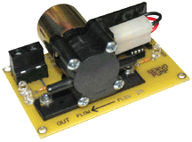
Servo Control Mini
Fluid Pump R/C Servo Controller Fluid Pump Module |
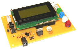
10-Ch MP3 Player /
Relay-Switch MP3 Playback Relay, Switch Controlled |
| IR Module Controller 8 - Ch On / Off Auto IR Control |
Servo Control Air
Valve R/C Servo Controller Air Module |
4-Ch PWM to Analog
Converter Servo PWM to 0-10 / 0-5 Vdc 80mA out |
| Fan / Servo / Relay
Controller 1-Ch SS Relay - Servo - Variable Fan |
MP3 / Relay/ PIR
Controller Audio MP3 - 4Ch SS Relay PIR Sensor |
Wizard-10 Plus 6 Servo, 2 Relays, MP3 Player |
| 1-Ch Analog Converter
Board PWM - Potentiometer 0-5, 0-10 VDC |
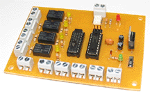
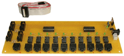
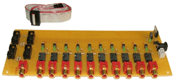
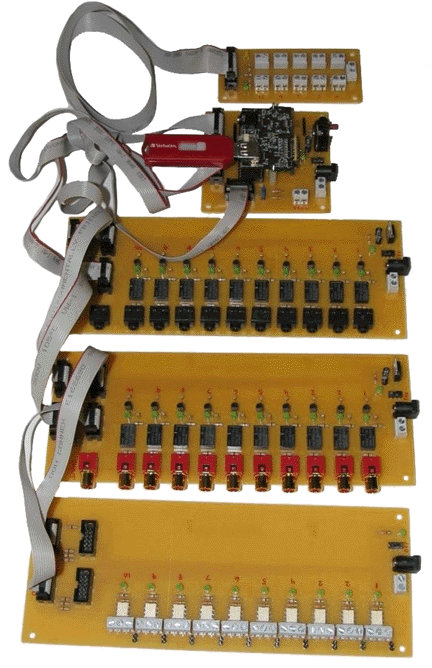
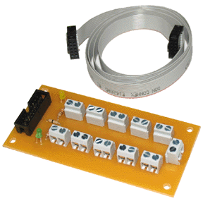
3 Input 12-Ch Relay
Controller 12 Ch Solid State Relays - Sw Selectable |
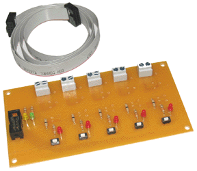
Modular Servo / Relay
Control 4 Servo, 1 Relays,Custom User Layout |
| 3- Channel Light
Sequencer LED / Light Bulb Power Driver |
Digital Potentiometer
Board Digital 10, 50, 100 K ohm potentiometer |
Linear / DC Motor Relay CW,CCW Rotation Control of DC Motor |
| 8-Ch Target Hit Game
Controller Game I/O Controller with Score Boards |
Game Time Controller Digital Timer with I/O Control features |
Random / VDC Servo
Control 12VDC Control -Random L/R/C Servo |
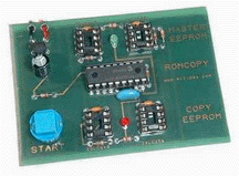
| EEPROM Master Copier EEPROM - Memory Chip Duplication |
||
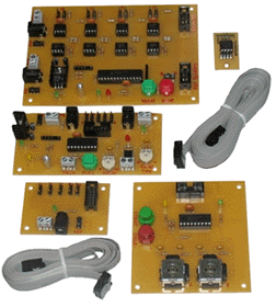
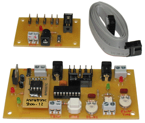
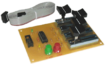
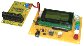
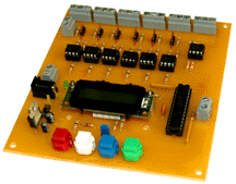
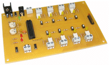
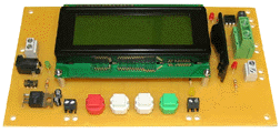
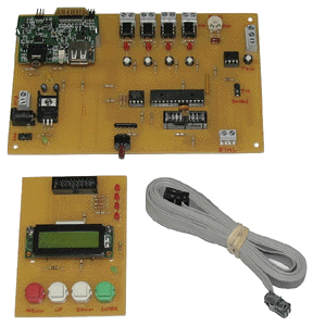
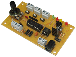
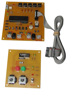
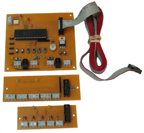
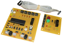
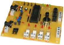
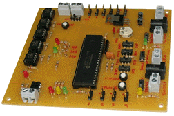
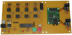
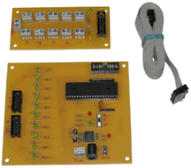
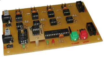
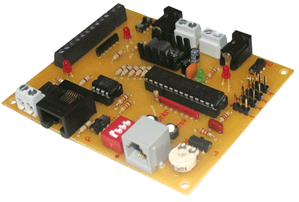
 Main
Logic Board Size:
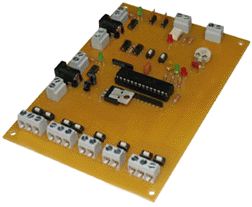
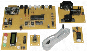
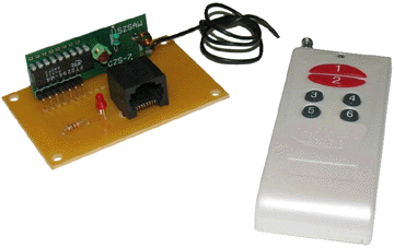
Main
Logic Board Size:  Optional
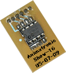
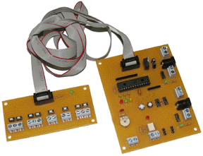
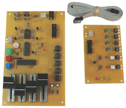
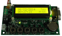
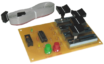
Remote LED
Optional
Remote LED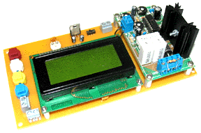
