
Welcome ...Product Categories ...What's New ...Sale Items ...Communications
E-Mail ...How to Order ...Order Form ...Catalog ...Legal Notices

| Mini Single
Servo Tester R/C servo tester / calibration module |
R/C Record
/ Playback (M5X) 4Ch Servo 1Ch Relay RC Controller |
R/C Servo
Relay Duo Control Switch Relays with R/C Transmitter |
| 4-CH Servo
Record / Playback R/C Interfaced 4-Ch Servo driver / board |
R/C 8-Ch
X2 Board Switcher 2 R/C Sources to 1 |
Servo
to Analog Converter Servo PWM / 0-10Vdc Variable Output |
| Linear
Actuator Motor Control R/C (PWM) Control of actuator motion |
High
Torque Servo - 84 in/lb R/C Controlled DC HD Motor |
R/C Servo
Booster Interface Module Boosts Servo Signal |
| Servo
Motor Controller Board R/C - DC Motor / Servo Controller |
High
Torque Servo - 156 in/lb R/C Controlled DC HD Motor |
R/C Servo
Slower Interface Module Slows Servo Motion |
| Servo
4-Ch Video Switcher 4 to 1 Ch Switched by Servo Output |
R/C -1
Ch SS Switch Board Switch relay On/Off R/C Transmitter |
R/C Solid
State Relay Board Switch 2 relays with R/C Transmitter |
| R/C Servo
Pneumatic Valve 1 Ch Air Valve Controller |
R/C Servo
Glitch Reducer Servo, Extensions - Noise Filter |
R/C LED
Light FX Control LED's Strobe / ON-OFF FX board |
| R/C Controlled
Fluid Pump Servo Controlled Mech. Pump |
R/C Navigation
LED Lights R/C controlled LED / FX Driver Board |
R/C Servo
Reverser Servo Rotation Change |
| R/C Servo
Stretcher Interface Module Extends Motion |
Camera
- R/C Servo Slower R/C Servo on Camera Motion Slower |
Dual
R/C Servo Slower Module Slows 2 - Servo Motion |
| Adjustable
Servo Slower Adjust Rates 1 - Servo |
Servo
Lead - Male / Male Hitec/Universal M-M Servo Jumper |
Assorted
R/C Servos Servomotors - Pico to Heavy Duty |
| R/C LED
Effects Board Receiver Interface LED 2-Ch FX |
R/C -1
Ch SS Relay Switch Servo output- 1Ch SS Relay 10Amp |
Servo
/ Water Sprayer Servo Controlled Spray Valve |
| R/C Video
Switcher - A 4 Ch V-Switch / Camera Power |
R/C Video
Switcher - B 4 Ch V-Switch / Camera Power |
R/C Servo
Switch Module 1Ch Control to 1-4 Servo Switch |
| R/C Duo
Board Switcher Switch 2 boards with R/C Transmitter |
R/C 2-Ch
Multiplexer Controller Switch Ch /Relays with R/C Transmitter |
Water
/ Air Valve Controller Servo Controlled Valves |
| Adjustable
Servo Slower Slow Rate Controllerfor Servo |
R/C Servo
Neutralizer Interface Module Slows Servo Creep |
R/C Single
Servo Duo Source Switch 2 servo boards to 1 servo input |
| Mini Air Pump Servo Controlled Mech. Pump |
Air Horn Servo Controlled Mech. Horn |
High Flow Fluid Pump Servo Controlled Mech. Pump |
| R/C Duo SS Relays
+ DC Volts 3 Ch with 2 Relays + 0-10 VDC Output |
R/C LED 10-FX Control R/C Iterface FX board 8-Ch output |
|
| R/C- Interface (M5-X) Record-Playback-Manual Control Board |
Hardware Description | |||||||||||||||
|
4-Ch Servo and 1-Ch Relay Board Size: |
4-Ch Servo and 1-Ch SS Relay (M5-X R/C Interface) This unique board will allow the manual control, recording and playback of approximately 10 minutes of (4ch) servo movement and (1ch) SS relay action via a radio control transmitter and receiver connection or optional non R/C interface board. The user can set the minimum and maximum limits for servo movement on board. All servo - relay information is stored in non-volatile EEprom memory. There is separate power connections for the board and servos, allowing large power servos to be used Modes of Operation: NOTE: This controller may be used with other PWM devices
such as Wizard boards, or other controller boards that generate
PWM, Digital Output Signals. |
|||||||||||||||
Custom Order, Please Contact Blue Point Engineering for Details |
||||||||||||||||
To Top of Page
| R/C Interface Programmer 4-Ch Servo Record and Stand-alone Playback Boards |
Hardware Description | |||||||||||||||||||||||||||||||||
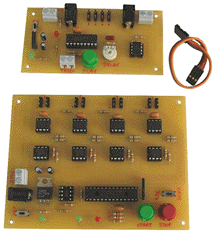 Playback Board Size: 4" L x 2" W x 7/8" H Recorder Board Size: 5" L x 3-3/4" W x 7/8" H Manual Application Notes |
4 Channel Servo Recorder and Stand-alone Playback Boards This unique controller board set consists of 2 boards, a 4-Channel
Servo Recorder board and a stand-alone 4-Channel Servo Playback
board. The programmer board is connected to a standard R/C receiver.
The Recorder Board will receive and record up to 4 servo signals
simultaneously and store them on individual on-board EEPROM's
as the R/C transmitter joysticks are operated. Up to 10 minutes
of servo activity can be recorded. Recorder Board require 7.5 to 24 Vdc at 200 mA supply (optional relay, power supplies, R/C Transmitter-Receiver, servos not included ) |
|||||||||||||||||||||||||||||||||
OUT OF STOCK Custom Order, Please Contact Blue Point Engineering for Details |
||||||||||||||||||||||||||||||||||
| Servo Motor Controller | Hardware Description | ||||||
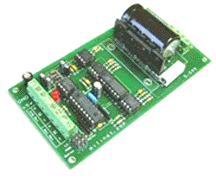 |
The (Servo) Motor controller allows standard DC motors to be controlled in the same manner as R/C type servo motors. The board may be configured to drive the DC motor simply as a variable speed, reversible motor or with the addition of a position feedback potentiometer, to create a powerful servo motor controller for accurate positioning purposes. The (Servo) Motor controller will drive DC motors rated at
up to 36V at 5A continuous current.(shipped as standard with
a 10A fuse) |
||||||
|
|||||||
| R/C 8-CH X2 Servo Multiplexer Switch Controller |
Hardware Description | |||||||||
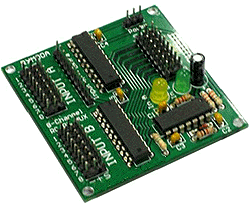 |
The 8 Channel RC RX MUX can be used with standard hobby radio control systems and servo controllers to allow easy switching of servo control between two signal sources using a 8th channel of Input A as the output selector. Signal sources can come from R/C receiver, autopilot or microcontroller that connected to Input A and Input B. Standard RC servos are connected to the output. This makes it ideal for applications in which user has two possible control sources and want to be able to switch between them on the fly. For example, user could connect two RC receivers at Input
A and Input B. The RC servos are connecting to 8 channels of
output. The 8th channel of Input A will decide whether the Input
A or Input B is in control, thereby setting up your own buddy-system
training setup. Another possible application would involve multiplexing
between an RC receiver and a servo controller, which will allow
you to switch between autonomous and manual control of a set
of servos. |
|||||||||
|
||||||||||
| R/C-Servo to Analog Converter | Hardware Description | |||||||||
 Small Board Size: 3-5/8" L x 1-1/4" W x 3/4" H PWM to Analog Instructions PWM to Analog Application |
This servo-analog converter board provides a two channel capability
of converting standard R/C servo PWM pulses to 0-10 Vdc and/or
0-5 Vdc outputs suitable for driving standard lighting dimmer
packs or any device that requires a 0-5 and/or 0-10 Vdc variable
controlled analog signal input. |
|||||||||
|
||||||||||
| R/C Controlled Duo SS Relays and Variable
DC Voltage Output Interface Board |
Hardware Description | |||||||||
|
-
Solid State Relays Rated:
|
Variable DC Voltage Output Interface Board This board was designed to take input from 3 separate R/C
servo signals and generate a 0-10 or 0-5VDC output (up to 80
mA) and control 2 sets of 2 Solid State Relays On and Off. Mode 1: Pulse Mode Mode 2: Toggle Mode Mode 3: Double Pulse Mode Mode 4: Double Toggle Mode |
|||||||||
|
||||||||||
| Mini Servo Tester | Hardware Description | ||||||
|
|
This small board will be found invaluable for projects and models using R/C type servos. Test and calibrate hobbyist "R/C - Radio Control"
type servos. In Automatic mode, Servo-Check produces a pulse stream
that makes the servo traverse smoothly through 90 degree at a
speed determined by the potentiometer setting (approx 0.5 to
5 secs / 90 degree ). In Manual mode, the servo position is fully adjustable from 0 to 90 degrees by using the thumbwheel. Manual mode generates a standard servo pulse stream. The width of the pulses varies between 1.0msecs and 2.0 msecs depending on the position of the potentiometer. Turning the potentiometer fully to either end of its travel will cause the LED to light indicating that either a 1.0 or 2.0 pulse width which should correspond with a servo angle of either 0 or 90 degrees. Additionally, as the potentiometer is turned, the LED will light at positions corresponding to15, 30, 45, 60 degrees and 75 degrees , thereby providing a field calibration setup. Works from standard 5-6 VDC supply and includes 3-pin header for all standard servos. Supplied built and tested, ready for immediate use. |
||||||
|
|||||||
| Servo Neutralizer | Item Description . | ||||||
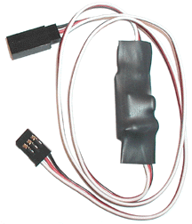 |
Stop servo creeping The Servo Neutralizer increases the servo's dead-band range
by 12hz causing the analog servo not to react to small signal
variations. |
||||||
|
|||||||
| Servo Stretcher | Item Description . | ||||||
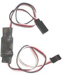 |
Extra range without distorting a servo signal. The 180° Servo Stretcher doubles the distance between
stops on the servo - effectively doubling the servo's range of
movement without affecting the speed of the servo. Mount the
180° Servo Stretcher just like you would a boosted extension.
Each stretcher comes in 24" lengths. CAUTION |
||||||
|
|||||||
| R/C Servo Slower | Item Description . | ||||||
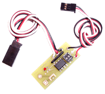 Board Size: 18mm W x 41mm L |
This inline servo signal processor lets you slow down the
travel movement of the servo, without effecting the servo performance It also doubles as a signal booster. |
||||||
|
|||||||
| Dual R/C Servo Slower | Item Description . | ||||||
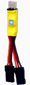 |
This Dual Adjustable Servo rate slower has the ability to indepenantly slow down two servos. A small potentiometer allows the servo end and end speed to be adjusted from less than 1 second to 5 seconds. The potentiometer also allows selection of the failsafe signal. When the rate reducer receives 10 bad signals in a row, it will default to failsafe mode and slowly move the servo to the failsafe position. This is especially important for Robot Combat gear One or both channels can be used at any time. The small potentiometer is adjusted in the following manner:
The center is the fastest servo speed. Turning the potentiometer
to the left or right will slow down the servo. Turning the potentiometer
to the left will enable the failsafe signal to be 1.0ms. Turning
the potentiometer to the right will enable the failsafe signal
to be 2.0ms. |
||||||
|
|||||||
| Servo Booster | Item Description . | ||||||
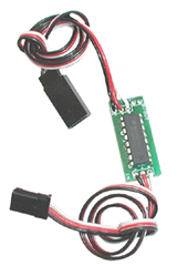 |
This 24" Servo Extension Booster for Futaba J servos
allows you to place your servos farther away from the signal
source in animatronics and robot projects. |
||||||
|
|||||||
| R/C Servo Reverser | Item Description . | ||||||
 |
The Servo Reverser will actually reverse the direction of
the R/C servo motor rotation. Information: Abilities: |
||||||
|
|||||||
| R/C Servo Glitch Reducer | Item Description . | ||||||
 |
The Glitch Reducer will eliminate most glitches before they get to the servos or electronic controllers. It will constantly output the last known 'good' signal and will suppress any input signal outside of the signal range. It will also suppress the random input signals that are within the signal range. Information: Abilities: Connection: NOTE: Not Intended for use on Digital Servos, or servos with FET booster installed. The total amount of control is dependent on the type of radio control or servo controller. |
||||||
|
|||||||
| Adjustable
Rate Servo Slower |
Item Description . | ||||||
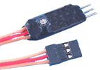 |
This adjustable servo rate slower has the ability to indepenantly
slow down a single servos. A small potentiometer allows the servo
speed to be adjusted from less than 1 second to 5 seconds. |
||||||
|
|||||||
| Servo Lead M-M Connector | Item Description | |||||||||
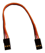 |
Servo Jumper - Male-Male connector ends. |
|||||||||
|
||||||||||
| Camera-R/C Servo Slower | Item Description . | ||||||
 |
The Camera Servo Slower is designed to smoothly move a R/C servo that is used for positioning a camera. The Camera Servo Slower works perfectly with a servo controller or an R/C transmitter stick. When the stick or controller is in the center position, the servo does not move. When the stick or controller potentiometer is moved to one side or another, the servo will slowly move to that position. When the camera is pointed in the correct direction, simply move the stick or controller back to the center to hold the servo at that position. The Camera Servo Slower also includes a failsafe mechanism that always outputs a correct servo signal. It will hold the servo at the last known position even if it looses the input signal from a glitch or control problem. Information:Weight: 1g NOTE: Not Intended for use on Digital Servos, or servos with FET booster installed. The total amount of control is dependent on the type of radio control or servo controller. |
||||||
|
|||||||
| R/C Servo Controlled 4-Ch Video Switcher |
Hardware Description | ||||||
|
|
Unique servo signal controlled electronic video switching
system which provides clean and fast switching between 4 video
channels to 1 channel. The Video switcher board will switch one of four video input
signals to a buffered video output line. The Video Switcher board
is suitable for all standard CCTV type video signals. System is excellent for operating 4 different cameras, and
sending video signal from one of the 4 cameras out to a remote
transmitter. Put full 360 degree vision on your robot, airplane,
animatronic character, or setup a covert operation with remote
control. |
||||||
|
|||||||
| R/C Servo Pneumatic Valve | Product Information | ||||||
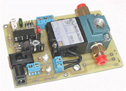 Board Size: 3-7/8" L x 2-5/8" W x 1-3/8" H |
.......New Design - R/C Servo Pneumatic Valve Unique R/C servo operated - Single-Acting 3-way valve. Runs directly from R/C receiver, Wizard, or Puppet boards, no interface, linkage or servo needed. Valve activation point ON and OFF default can be set. This valve can also be used to operate larger pilot-operated valves, Props, Robot modules, or any where you need programmable air control. PC board can be split with the valve at a different location than the controller electronics. Board Size. 3-7/8" L x 2-5/8" W x 1-3/8" H (12 Vdc power supply, R/C receiver, Wizard Puppet controllers, servo wire lead not included ) |
||||||
Custom Order, Please Contact Blue Point Engineering for Details |
|||||||
| R/C LED Strobe and All ON/OFF FX Controller |
Item Description | |||||||||
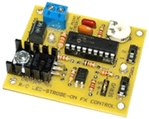 Board Size: 2-1/4" L x 2" W x 1/2" H LED Output 12VDC @ 2 Amp |
This board allows the activation of a 12 VDC LED/ Strip in
a Constant On/Off or in a Strobing Effect mode by using a standard
R/C joystick and it's movements. |
|||||||||
|
||||||||||
| R/C
Controlled Navigation Lighting Board |
Item Description | |||||||||
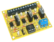 LED Output 12VDC 2 Amp per channel Board Size: 2-1/4" L x 2" W x 1" H 1-Ch controls all Three Group Effects |
(DRONE, UAV, Robot, Airplane) This board was designed to allow the control of 3 groups or channels of LED's or LED strips as Navigation Lighting by using the control (PWM) signal from a R/C system Receiver and Remote Transmitter. Group One: Red, (Starboard), Green (Port) and White LEDs /
Strips. |
|||||||||
|
||||||||||
| R/C LED 10-Effects Board | Hardware Description | ||||||
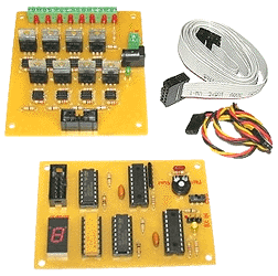 -- |
The control board is designed to allow the manual selection
of 10 different effect modes and the activation ON/OFF of 8-LED
Strip Channels to playback the selected Effects by remote R/C
Transmitter using servo (PWM) output signals. There are 2 boards
to this project a Main Board and a Remote board This board
allows the manual activation fof10 different light effect modes
for 8-channels of 12 VDC LED strips using servo CH-1 of an R/C
Transmitter joystick movement (Left) to toggle, select the effects
mode 0-9, then joystick movement (Right) to activate the LED
Strips ON / OFF with the effect mode selected. The board is powered
by the +5V coming from the servo connectors and the LED strips
are connected to their own pass through power supply 12VDC. RIGHT Movement - ON / OFF Toggle - LED Strips Effect Modes: Mode 0: All LED's ON |
||||||
|
|||||||
| R/C LED Effects Board | Hardware Description | ||||||
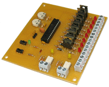 |
This unique board will allow use of a RC servo control joystick
to control eight channels of remote DC lights (LED or incandescent)
in 2 different sequences. Each channel is capable of driving
up to 200 mA of lighting. An on-board LED for each channel indicates
that the channel is active. Two on-board SS relays one
for each sequence - will also activate depending on which sequence
is selected. A Mode Selection Switch will allow the user to toggle
between Momentary On or Toggle On/Off modes. For example, with
the Mode switched to Mode 1 (Momentary On), when the RC joystick
is tilted to the left, Sequence 1 will start and Relay 1 will
activate. Sequence 1 and Relay 1 will continue to be active as
long as the joystick stays in the left position. When the joystick
is in the center position, neither sequence will be selected.
In Mode 2 (Toggle On/Off), when the joystick is tilted to the
left and then returned to the center position, Sequence 1 will
start and Relay 1 will activate. The sequence will continue and
the relay will stay activated as long as the joystick remains
in the center position. To stop this sequence, the user must
tilt the joystick to the left a second time, toggling the sequence
off. The same applies for Sequence 2. There are 2 potentiometers
on board, one for each sequence that allows the user to control
the rate of each sequence. The board has an on-board On/Off switch.
Power to the board is supplied by the 5V line of the RC Servo
connection and should have sufficient current to drive the board
and all of the eight light channels (~2A max). Sequence 2 Strobe: |
||||||
|
|||||||
| R/C Video Switcher- A | Hardware Description | |||||||||
|
Click on Image for a Larger View |
Video RCAConnections and Camera Power Connections Unique servo signal controlled video switch was designed to
allow the use of a R/C servo controller joystick (R/C Transmitter
/ Wizard Board) to give user the ability to select which video
input to be sent as an output ( to remote RF Vide transmitter,
monitor system, video recorder, etc). Up to 4 separate video
inputs can be attached to the boards. Depending on the position
of the joystick, one of the 4 inputs is selected and switched
to the output. Also, each of the 4 video cameras can be powered
from the board via separate power connections. The power is supplied
to the camera continuously (they are not switched as are the
video inputs). A yellow LED indicates which video input is selected. The inputs are selected based on the servo signal sent to
the board. There is a SS relay on the board that activates as soon as power is applied to the board. ( 2 Amp load - wire terminal block for quick connection ) The difference between R/C Video Switcher A and R/C Video
Switcher B is that 2-position terminal blocks are substituted
for the 2.1 mm power connectors and the RCA jacks. |
|||||||||
|
||||||||||
| R/C Video Switcher - B | Hardware Description | |||||||||
|
Click on Image for a Larger View |
Wire Termainal Blocks and Camera Power Connections Unique servo signal controlled video switch was designed to
allow the use of a R/C servo controller joystick (R/C Transmitter
/ Wizard Board) to give user the ability to select which video
input to be sent as an output ( to remote RF Vide transmitter,
monitor system, video recorder, etc). Up to 4 separate video
inputs can be attached to the boards. Depending on the position
of the joystick, one of the 4 inputs is selected and switched
to the output. Also, each of the 4 video cameras can be powered
from the board via separate power connections. The power is supplied
to the camera continuously (they are not switched as are the
video inputs). A yellow LED indicates which video input is selected. The inputs are selected based on the servo signal sent to
the board. There is a SS relay on the board that activates as soon as power is applied to the board. ( 2 Amp load - wire terminal block for quick connection ) The difference between R/C Video Switcher A and R/C Video
Switcher B is that 2-position terminal blocks are substituted
for the 2.1 mm power connectors and the RCA jacks. |
|||||||||
|
||||||||||
| 1-Ch to 4-Ch R/C Servo Switching Controller |
Hardware Description | |||||||||
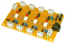 Board Size Approx: 4-1/8" L x 2-1/2" W x 1" H Solid State Relays Rated: 1 - 12 VDC at 1 Amp Application Example 1 controller operating 4 different servos |
This module is designed to switch a single R/C channel control signal to four different set of servos individually or as any group 1-4. Module allows each servo to be controlled independently from
the standard control signal (PWM) but can be switched to control
different connected servos. |
|||||||||
|
||||||||||
| R/C Duo Board Servo Output Switch Controller |
Hardware Description | |||||||||
|
|
The R/C - Wizard Servo Switch board will switch 1-6 individual servo PWM signals coming from a standard R/C receiver or all 6 individual servo PWM signals coming from a Wizard Board to 6 shared common servo lines when switched on / off by R/C transmitter-receiver Aux Ch. The user will manually control 1-6 servos by operating the
R/C transmitter When Ch-AUX of the R/C transmitter-receiver is de-activated
it will switch all 6 channels from the Wizard Board back to the
R/C transmitter-receiver control for manual operation of the
1-6 shared servos. |
|||||||||
Custom Order, Please Contact Blue Point Engineering for Details |
||||||||||
| R/C 2-Ch Servo / Relay Multiplex Switch Controller Board |
Hardware Description | |||||||||
|
|
This board allows the use of an RC controller to select outputs for two servo inputs and control two SS relays. The Servo outputs and relays are controlled separately. Two servo inputs can be output to 6 different outputs. The RC joystick allows the user to select which of the 6 outputs to send the two servo inputs to. Moving the joystick left decrements the channel, moving it right increments the channel. The channel number selected is displayed on a 7 segment LED display. Once a channel has been selected, a 2 second time delay is started before enabling the outputs. After the delay has expired, the Channel Active Indicator (decimal point on LED Display) lights and the incoming servo signals are routed to the selected outputs. Power for the servos can be supplied by a single power supply (by inserting the shorting block next to the servo connector), or any servo can have a separate power source. This is attached at the terminal block just above the servo connector. In this case, the shorting block must be removed. All servo signals are optically isolated from the inputs. The relays are also controlled by RC joysticks. Each relay is controlled by a separate joystick. Moving either joystick to the right will activate the associated relay. When the joystick is returned to the center, the relay is deactivated. The board is powered by 12VDC and is attached to the Power Input Terminal block or the 2.1mm Power Jack. A terminal block is also supplied to allow the attachment of a remote switch which will bypass the on-board switch. |
|||||||||
|
||||||||||
| Small R/C - 1 Ch Switch Board 2 Amp Solid State Relay |
Hardware Description | |||||||||
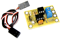 Small Board Size: 1-3/8" L x 1-1/4" W x 7/8" H Jumper Wire M to M 6" long |
2 Amp Solid State Relay This PIC micro controlled board will take a RC Servo signal
from any standard RC transmitter and receiver or Wizard Servo
board and toggle the operation of a 2 amp Solid State DC Relay.
When there is no servo signal being input, the relay will be
off. When the servo signal is about 1.0mS then the relay will
come on and will stay on until the servo signal goes to about
2.0 mS and then the relay will go off. (R/C transmnitter, receiver, Wizard servo board, power supply not included) |
|||||||||
|
||||||||||
| R/C 2 Ch Solid State Relay Interface Board |
Hardware Description | |||||||||
|
Board Size: |
New Enhanced Design Connect this Microprocessor assisted, solid state digital
switch board to you radio control receiver and have the option
of manually controlling two relay outputs ON or OFF with your
R/C transmitter joystick. Solid State Relays Rated: SS Relay Switching Time: |
|||||||||
|
||||||||||
| Adjustable R/C Servo Slower Interface Board |
Hardware Description | ||||||
|
|
This unique board will control the moving speed of a servo output. On board potentiometer allows for the servo to move from very slow to normal speed. The controller will slow the servo movement, but keep the same PWM control. |
||||||
Custom Order, Please Contact Blue Point Engineering for Details |
|||||||
| R/C Servo Solid State Relay Interface Board with Duo Control Options |
Hardware Description | |||||||||
|
Solid State Relays Rated: |
with Duo Control Options New Lower Pricing This board allows the activation of two Solid State 2-Amp
Relays by using the standard R/C Transmitter joystick. It has
4 modes of operation that are selected by the placement of 2
jumpers. The board is powered by the +5V coming from the servo
connector. |
|||||||||
|
||||||||||
| R/C - 1 Ch Switch Board 10 Amp Solid State Relay |
Hardware Description | |||||||||
|
|
10 Amp Solid State Relay This board will take a RC Servo signal from any standard RC
transmitter and receiver or Wizard Servo board and toggle the
operation of a10 amp Solid State DC Relay. When there is no servo
signal being input, the relay will be off. When the servo signal
is about 1 mS then the relay will come on and will stay on until
the servo signal goes to about 2 mS and then the relay will go
off. The relay will then stay off until the servo signal goes
back to about 1 mS. (R/C transmnitter, receiver, Wizard servo board, power supply not included) |
|||||||||
|
||||||||||
| Linear Actuator / DC Motor Controller by R/C Interface |
Hardware Description | ||||||||||||
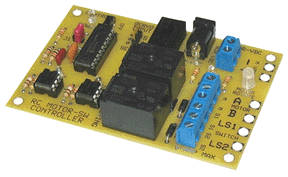 Board Size: 3-7/8" L x 2-5/8" W x 3/4" H |
New Design This unique board was designed to allow the directional control
of a Linear Actuator (IN / OUT) or DC Motor Rotation (CW / CCW)
by using a R/C servo output channel (PWM Signal) to control the
DC Motor movements / positions. Controller has on-board PIC Microprocessor for R/C to Relay
Control. 3-Pin header for quick servo wire connection from R/C
receiver or Wizard board. |
||||||||||||
|
|||||||||||||
| R/C Single Servo Duo Source Switching Board |
Hardware Description | |||||||||
|
|
This board allows the control of a single servo by two different
sources. One source can be from a hard-wired controller (like
a Wizard -12 Board)
and the other source can be from a R/C
receiver. There is a switch on the board that when switched
to the "W" position will lock out the R/C source. The
servo attached to the board at the SO header will only respond
to the Wizard board attached to the MSI header. |
|||||||||
|
||||||||||
| Servo Wire | Item Description | |||||||||
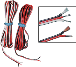 |
SERVO WIRE |
|||||||||
|
||||||||||
| Mini Air Pump - 50 | Hardware Description | ||||||||||||
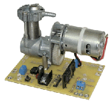 Click on Image for Closeup Views Pump Size: Length: 5-3/4" Width: 1-1/2" Height: 3-1/2" Mini Air Pump Power Driver Board 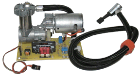 Mini Air Pump with Optional R/C Servo Control Board |
12Vdc operated Mini Air Pump. (Hose, gauge, clamp, Air tank, power supply not included)
Mini Air Pump R/C Power Driver Board (VDC output power supply not included) ......... Mini Air Pump Power Driver Board |
||||||||||||
Custom Order, Please Contact Blue Point Engineering for Details |
|||||||||||||
| Mini Fluid Pump | Hardware Description | |||||||||
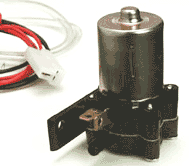 Pump Instructions 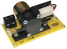 |
Small 12 Volt DC powered pump for moving fluids. 12 Vdc operated electric pump Pump comes with connection tubing, electrical hook up wire,
tube adapter, plastic tube "T" Power supply not included. |
|||||||||
|
||||||||||
| High Flow Fluid Pump | Hardware Description | |||||||||
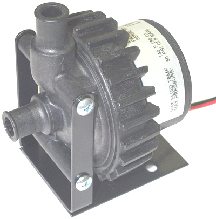 Pump Size: 2.33" W x 3.74" L x 4.13" H 1/2" Inlet / Outlet (Discharge) 12Vdc - 2 Amp power requirement 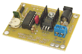 |
The High Flow Fluid Pump is a very reliability, high pressure small industrial pump. The unique design of this pump contains only one moving part: the magnetically driven spherical impeller spins on a single ceramic bearing,. The pump is completely plug-and-play and connects directly to a BPE Servo or Motor Controller Board. The compact design, quiet and powerful motor make it ideally suited for heavy duty use in environments where space is at a premium and very little noise is generated. Technical specifications: - Pump
Spheric Impeller Drawing Pump controller, power supply, hoses not included. |
|||||||||
OUT OF STOCK Custom Order, Please Contact Blue Point Engineering for Details |
||||||||||
|
Water / Air Valve Remote Switched Board |
Hardware Description | |||||||||||||||
|
Click on Image for closeup view
|
Servo / Remote Switch Controlled Switched On/ Off Boards Servo Controlled Switched On/ Off Board
Remote Switched On/Off Controller
|
|||||||||||||||
|
||||||||||||||||
| Water Sprayer/ Squirter Controller Boards Remote Switched Board Servo Switched Board |
Hardware Description | ||||||||||||
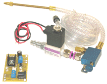 Click on Image for closeup view |
Air Operated Water Spray System Information Servo Controlled Switched On / Off Air Valve / Sprayer
Control |
||||||||||||
|
|||||||||||||
Copyright © 2015 Blue Point Engineering LLC., All Rights Reserved