Welcome ...Product Categories ...What's New ...Sale Items ...Communications
E-Mail ...How to Order ...Order Form ...Catalog ...Legal Notices
. Control Boards / Devices: Relay Controller Products
.Back to Controller ListingWizard - 2 Control Board
4 / 8 / Servo / Digital OutputWizard - 9 Control Board
Programmable Duo Relays (2)8 - Ch SS Relay Controller
8 Solid State Relays ON / OFF outputWizard - 4 Control Board
4 - User Programmable Relays8-Ch Sequence / Random Relay
8 Ch Power Switched On/Off Outputs2 Ch Programmable Relay
1 and 2 Channel Relay BoardsProgrammable Single Relay -A
1 - User Programmable Silent RelayDigital SS Relay Controller
Programmable SS Relay Controller1 Ch Programmable Relays
1 and 2 Channel Relay BoardsProgrammable Single Relay - B
1 - Programmable Relay -Large LoadProgrammed Random Trigger
Random Control of 3 SS RelaysSequence 3 Ch - SS Relays
Remote Switch 3 Ch Relay Sequence3- Event Sequence Relay Board
3 Programmable Relays with Sequence8 Ch Mini SS Relay Board
8 Switched SS Relays/Remote SwitchesRandom 8-Ch Relay Board
Adjustable Random Relays On/OffPIR Sensor with SS Relay
Mini Solid State Relay SensorTTL-1 Ch Relay Board
1ch TTL Control Signal to 1ch RelayTTL-4 Ch Relay Board
4ch TTL Control Signal to 4ch RelayTTL-1 Ch Latching Relay
TTL Signal 1ch Relay Latched OutputTime Delay Relay Board
Programmable Timer - 1Ch RelayInterval Timer Relay Board
Programmable 1ch Relay On/Off12-Ch Toggle / Latching Relays
Mechanical Relay Switching Board4/2 Ch Relay Output Switch
2-4 Ch Sw Relay Output ControlSound Activated Delay Relay
Sound to Power Delay Relay Module1-4 Ch Solid-State Switcher
1 Ch Input to 1-4 Ch Output10 Amp SS AC Relay Module
DC Solid State AC Relay Interface5 Amp SS AC Relay Module
DC input Solid State AC RelaySolid State AC Dimmer Module
DC Input- Dim Up/Dowm AC Devices15/25 Amp SS AC Relay Module
DC Solid State AC Relay InterfaceSolid State Relay Hand Switch
Switch Connection / SS RelayMini SS Relay Module
1Ch -1Amp / 60 VDC RelayMicro Solid State Relay Module
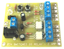
Add-on 1ch Output 2 Amp SS Relay2 Ch Solid-State Relay
2 Ch Input Relay ControllerUniversal Sensor with SS Relay
Sensor Connection / Solid State RelaySound Activated Relay Module
Sound to Relay ModuleMini PIR Sensor with SS Relay
Mini Solid State Relay SensorRemote 4-Ch Program SS Relays
4 Channel Solid State DC Relays-ProgramProgrammable 1-Ch SS Relay
Programmable Relay -Time On/Off, LoopTime Delay Module
Preprogrammed Power Delay RelayProgram 4- Ch AC Relay Board
4 Ch Solid State AC / 25 Amp RelaysR/C -1 Ch Relay Switch Board
1 Ch Servo to SS Relay 10 Amp10-Ch SS Programmable Relay
10 Ch Solid State DC Relays-Program2-Ch Programmable Relay
Program 2-Ch Relays with Options3 Input 12-Ch Relay Controller
12 Ch Solid State Relays - Sw Selectable4- Ch with 10 SS Relay Board
Program 4-Ch / 10 Solid State RelaysAC Relay with 5/9 VDC outputs
AC Switch with 5 Volts DC outputRelay / Switch AC Power SW
Relay-Switch Controlled AC On/OffSS Relay Module - A
10 Amp AC Control - ON / OFFServo Control AC Relay SW
R/C Servo On/Off AC Power SwitchProgram 4-Ch SS / AC Relay
AC-15 Amp 4-Solid State RelaysSS Dimmer Module - B
10 Amp AC Dimmer ModuleDTMF Programmable Relays
8-Ch SS Relay Control by SoundProgram Event Time Relay
3-Time Periods / Triggered 10A RelayLatching Reed Switch
Reed Switch / Magnet RelaySwitch Control DC Motor Relay
10 Amp DC - Switch Input Control12VDC Input Motor Relay
10 Amp DC - 12 VDC Input ControlSwitching DC Relay Boards
10-15 Amp Isolated Switch/Power RelaysSound Activated Output Driver
Sound to Power Relay Module
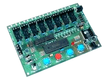
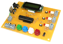
Wizard - 2 Board 4 / 8 - Servo / Digital Controller |
Hardware Description | |||||||||||||||
Wizard-2 Board Document
|
The Wizard - 2 Board will record / playback up to 5 minutes
of action for up to 4 -R/C type servos and 4 - digital outputs
or can be selected to operate 8 digital outputs with on board
relays or direct digital signal output connection pads each with
5 minutes also per channel of recording time. The board also
incorporates features such as looping playback action with variable
delay between start-up on power up and sensor input. A terminal
connection block for remote switch, pressure pad or synch signal
from other device to initiate playback sequences is built on
board also. - 4 Servo output channels, each capable of recording and playback
of up to 5 minutes of action. |
|||||||||||||||
|
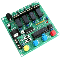
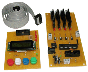
Wizard - 4 Board Programmable 4-Channel Relay Control |
Hardware Description | |||||||||
Controller is pre-assembled and tested. Controller has 7-bit Resolution. ,,, Wizard-4 Manual Board Size: 4" L x 4" W x 1/2" H Wizard - 4 Board Document Application Examples Product Video |
( Programmable 4-Channel Relay Module ) The Wizard- 4 Controller Board or Programmable Supplied built and tested. |
|||||||||
|
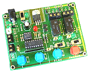
Wizard - 9 Board Programmable Duo Relay Controller |
Hardware Description | |||||||||
Board Size: 4" L x 3" W x 1/2"H |
The Wizard 9 board will record and playback up to 25 minutes of action for up to 2 digital / relay outputs. The board also incorporates features such as looping action with variable delay between loops, auto start-up on power up and a connection interface for a PIR, remote switch or pressure pad to initiate playback. Specifications: 2 Digital channels- either 0/5V @ 100mA outputs or mechanical
relay rated 30V @ 2Amps to wire terminal blocks,. |
|||||||||
|
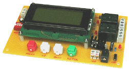
Programmable - 2 Ch Relays with Relay Output Options |
Hardware Description | ||||||
Board Size: Aprox 5-7/8" L x 3-5/8" W x 1" H Relays Rated: 10 Amp Board Power Supply 9-12 V DC @ 1 Amp ,,,Instructional Manual |
with relay output options. This board is designed to allow the timed-control of two 10A
relays in several fashions. Timing is entered via menu-driven
LCD and stored in non-volatile memory. Operational modes are
set using a 4-position DIP switch. Relays have LED's to indicate
activity, Power LED. On and Off on-board power switch. Wire terminal
block for remote trigger. |
||||||
|
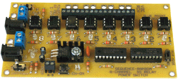
8-Channel Sequence / Random and Automatic Relay Board |
Hardware Description | |||||||||||||||
Board Size Approx: 6" L x 2-3/4" W x 5/8" H |
This unique board is designed to allow you to distribute Power
from a single input to one of 8 outputs in sequence, random or
sequence automatic when a trigger event (dry contact closure
or tactile switch press) is activated. |
|||||||||||||||
|
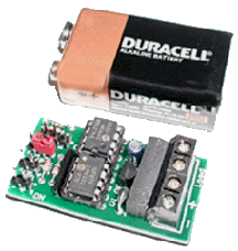
Programmable Single Channel Relay A Module |
Hardware Description | |||||||||
Controller is pre-assembled and tested. Board Size: 1-7/8" L x 1" W x 5/8" H Programmable Relay Document Programmable Relay Applications |
The Programmable Single Relay Module has sufficient memory to record up to 4.5 hours of Relay ON/OFF programmed actions. Programming is easily done on-board with a set of jumpers. Supplied built and tested. |
|||||||||
|
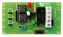
Programmable Single Channel| Relay B Module |
Hardware Description | |||||||||
Controller is pre-assembled and tested. Board Size 3" L x 1-1/2" W x 9/8" H ,,,Programmable Relay Applications |
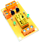
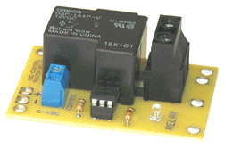
The Programmable Single Relay - B Module is similar to the Relay - A module with memory to record up to 4.5 hours of Relay ON / OFF programmed actions, but has a bigger relay on-board to handle larger loads ( 24 Vdc @ 2 amp), power On / Off switch, status LED's and on-board solder pads for permanent wiring directly to board. Programming is easily done on-board with a set of jumpers. Supplied built and tested. |
|||||||||
|
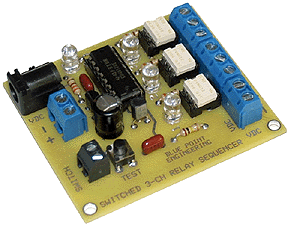
Sequence 3 Ch -Relay Control Module 3- Sequential Solid State Relay Outputs |
Hardware Description | |||||||||
Board Size: 2-1/2" L x 2-1/4" W x 5/8" H Board is pre-assembled and tested. |
Remote Switch, or switch and Microprocesson on-board will
operate 3 - Solid State relays in sequence starting at relay
-1 as a remote switch / relay input is activated momentary on
and move up each channel as remote switch is activated Relays are rated 9-12 Vdc @ 2 Amp Solid State Relay-1 is on when board is first powered on |
|||||||||
|
8 - Ch Solid State DC Relay Controller | Hardware Description | |||||||||
Board Size: |
Control Board will record and playback up to 13 minutes of Solid State Relay switched ON and OFF output action. The board incorporates many features such as looping playback with variable delay between loops. Recording sessions are built up on a channel by channel process - no complex programming is required. During recording, all previously recorded channels are re-played to aid synchronization the current channel being programmed. Programming is easily done, with a set of push button keys and control potentiometer built onto the board. No host computer or other programming device is needed to operate the board, Board is silent, no mechanical relay noise when operating. Specifications: Power supply not included. |
|||||||||
|
3 Input 12- Channel Selectable Solid State Relay Board |
Hardware Description | ||||||||||||
Main
Logic Board Size: 7" L x 5" W x5/8" H LED Status Board Size: 5-3/4" L x 4 1/2" W x 1" H Optional Remote LED Status Board Size: 5-3/4" L x 4 1/2" W x 1" H |
Description: Operation: Requires power supply of 9V DC at 1 Amp |
||||||||||||
|
Digital Programmable Solid State DC Relay Controller |
Hardware Description | ||||||
Board Size: 4-3/4" Long x 2-3/8" Wide x 1" High Relay Rated: 12 Vdc at 1 Amp Power Supply 7-24 V DC @ 100 mAmp Power Supply .. Board is pre-assembled and tested. Controller Instructions |
Digital Relay Board can be programmed with a Delay time, a
Relay On Time and a Loop function. All settings are stored in
non-volatile memory. There is a 4-Line by 16 Character back-lit
LCD that is the user interface for programming the different
modes of operation. These modes are set up and initiated using
a menu-driven display with input being made by on board pushbuttons. |
||||||
|
1-Ch and 2-Ch Programmable Relay Controllers |
Hardware Description | |||||||||
Board Sizes: |
Programmable Relay Board - 1 Programmable Relay Board - 2 Specifications: Power supply not included. |
|||||||||
|
Programmable Event Sequence Relay Board |
Hardware Description | ||||||
,,,Operating Instructions |
This board controls the timed operation of 3 relays. For each
relay there is a delay. The order that the delays and relay triggering
is: Delay 1, Relay 1, Delay 2, Relay 2, Delay 3, Relay 3. The
time for each Sequence can be set from 0 to 4 minutes 15 seconds
in X second increments. Board requires 12Vdc @ 800 mA for operation |
||||||
|
Programmable 3-Time Sequence Relay Board |
Hardware Description | ||||||||||||
Board Sizes: 4-5/8" L x 2-3/8" W x 7/8" H 12Vdc @ 1 Amp Power Supply Required |
This board was designed to control the activation of a single
prop. It has 3 user-adjustable timing sequences that are set
by 3 on-board pots. (1) The first timing sequence, once the board
has been triggered, delays the activation of the prop. This period
can last from 1 to 60 seconds. This timing sequence begins as
soon as the trigger event occurs and is intended to allow the
support actor to move into position before the prop activates.
(2) The second timing sequence begins as soon as the first timing
sequence has finished. During this timing sequence, the on-board
relay is activated and will stay on for this entire timing sequence.
This timing sequence can last from 1 second to 5 minutes. (3)
The final timing sequence begins as soon as the second timing
sequence ends. The relay is off during this timing sequence.
This sequence is intended to prevent the board from being re-triggered
again for the specified time (1 second to 5 minutes) allowing
the audiance / support actor to move on. Board requires 12Vdc @ 1Amp for operation
|
||||||||||||
|
8 - Ch Switched Input / Output Solid-State Relay Controller |
Hardware Description | |||||||||
Board Size: |
Solid State DC Relay Control Board This board allows the individual control of 8 Solid State Relays. For each relay, the user can program an On Time, an Off Time and a Loop Time. The times can be different for each relay and the time intervals can range from 0 seconds to 5 minutes. The relays can be triggered individually or in sequence by applying a dry switch closure at the respective terminal or pressing the associated test pushbutton. An AutoStart switch is provided so that, if switched on, the board will immediately go to waiting for a trigger event to start the playback. The user enters all times via menu-driven LCD. The board incorporates many features such as looping playback,
sequence of relays from a single input, relay cascading where
relays activate one after another based on the programmed times
once triggered. Specifications: Power supply not included. |
|||||||||
|
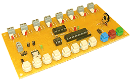
Random 8-Ch Relay Board | Hardware Description | ||||||
Board Size: 6-1/4" L x 4" W x 1" H Relay Rated: 12 Vdc at 1 Amp .. Application Setup Overview |
This unique board will allow the control of 8 Solid State relays in four modes of operation. Each relay has a test button and indicator. There are 2 potentiometers that will control the on times and off times (as appropriate) of the relays. Two Mode Indicators will indicate which of the 4 modes is selected. For each of the relays, there is a terminal block for the contacts. Also, all relay contacts are brought to a 16-pin ribbon cable connector for remote output use. Mode 1: - Manual / Random Relay Activation when triggered |
||||||
|
DTMF Programmable SS Relay Controller |
Hardware Description | ||||||
DTMF Generator Board Size: 4-5/8" L x 2-3/8" W x 5/8" H DTMF Translator Board Size: 3-4/5" L x 3-3/4" W x 5/8" H Relay Rated: 12 Vdc at 1 Amp |
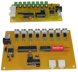
These very unique boards were designed to allow the control of 8 solid State Relays using DTMF tones. There are 2 boards A DTMF Generator and a DTMF Translator. The Generator board generates a DTMF tone that is associated with one of the 8 on-board pushbuttons. This tone is output to the two 1/8" stereo jacks on the board. The tone is only present on the left channel. The right channel is not used. One jack will go to the Translator board and the other will go to a computer for recording or to a set of amplified speakers. The translator board receives the DTMF signal from either
the Generator board or some device that has the DTMF signal recorded
on the left channel of audio.(MP3 Audio Playback player). This
signal goes into the DTMF/Audio Input Jack. The DTMF signal on
the left channel is passed to the board for translation. If the
board receives a valid DTMF signal, the Valid Transmit LED will
light and the associated relay will be activated. There is an
8-position DIP switch that will control how the relay operates
latching or momentary. If a DIP switch is in the ON position,
the associated relay will operate in the latching mode, meaning
that the relay will activate and stay activated until the next
specific DTMF tone is received and then it will turn off. Momentary
means that the relay will activate only for as long as the DTMF
tone for that relay is present. |
||||||
|
Programmable Random Trigger Control Board |
Hardware Description | ||||||
Board Size Approx: 4-3/4" L x 3-3/4" W x 1" H Relay Rated: 12 Vdc at 1 Amp |
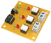
Control Board This board allows the user to simultaneously trigger 1-3 solid
state relays after a random interval has expired. The random
time interval can be limited to any time within 1 second to 15
minutes. The random time interval starts when a dry contact closure
occurs at the Trigger 1 terminal block. Solid-State Relays rated 12Vdc @ 1 Amp each Requires power supply ranging from 7.5V to 24V DC at 100 mA. |
||||||
|
Remote Programmable 4-Ch 10 Amp SS DC Relay Board |
Hardware Description | ||||||
Board Sizes: Relay Board: 5-1/2" L x 2-5/8" W x 1-1/4" H Programming Board: 2-1/2" L x 2-5/8" W x 1" H Connection Cable: 3 Foot |
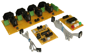
Solid State DC Relay Board This is a 4-Channel Programmable Relay board. The relays are
Solid State relays rated at 10 Amp DC Voltage each. Programming
is accomplished via a Programming Interface board that is connected
to the Relay board by a 3 foot ribbon cable. The user is prompted
through menus for information such as AutoStart, Loop, and relay
program entry. Each of the relays can be manually activated using
the associated mini tactile switch located just below the relay.
When the relay is activated, a LED just below the relay lights
and a LED on the Programming Board lights as well. The Programming
Interface board can be attached during playback or removed. If
it is attached, the user can get playback status displayed on
the LCD. Playback can be initiated by pressing the Enter Button
on the Programming Interface Board, if connected, or via a dry
contact closure at the remote trigger terminal on the Relay Board.
When the board is triggered, a 80 mS Synch Pulse is present at
the Synch terminal. The user can program up to 15 minutes of
relay activity and up to a 5 minute delay time between playbacks
if the Loop option is selected. If AutoStart is selected, as
soon as the board is powered up, it goes directly to Run Mode
and waits for a trigger event to occur. |
||||||
|
Programmable 1 - Ch 3 Amp Solid State DC Relay Board |
Hardware Description | |||||||||
Board Sizes: Relay Board: 3-1/4" L x 2-1/4" W x 1" H Programming Board: 3-1/4" L x 2-3/4" W x 3/4" H Connection Cable: 12" |
Solid State DC Relay Board This unique system consists of 2 boards a Programming
Board and a Playback Board. It is designed to allow the user
to program the length of time that a 3 Amp Solid State relay
stays on and stays off once triggered. The user can also program
the on and off cycle to repeat continuously. The relay on time
can range from 1 second to 10 minutes. The off time can range
from 1 second to 30 minutes. When programming, the Programming
Board is connected to the Playback Board via a 12" ribbon
cable. After programming, the Programming Board can be removed
from the Playback Board. The Playback Board will then be in Playback
Mode, awaiting a trigger (dry contact closure). Once triggered,
the playback Board will operate the SS relay. If the Programming
Board remains attached to the Playback Board, the LCD will display
the relay status and count down the time remaining for the on
and off times. All settings will be stored in non-volatile memory.
Board will work on 7.5 to 24VDC. The status of the SS relay is
also indicted by a red LED next to the relay. Solid State Relay = 3 Amp |
|||||||||
|
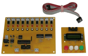
10 - Ch Switched Input / Output Solid-State DC Relay Controller |
Hardware Description | |||||||||
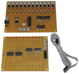
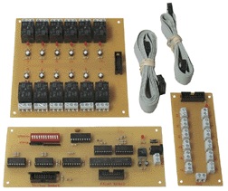
Main Board Size: |
DC Relay Control Board This is a 42 minute, 10-Channel User Programmable Relay board.
The relays are Solid State relays rated at 1 Amp each. Programming
is accomplished via a Programming Interface board that is connected
to the Relay board via a 6 foot ribbon cable. The user is prompted
via menus for information such as AutoStart, Loop, and relay
program entry. Each of the relays can be manually activated using
the associated mini tactile switch located just below the relay.
When the relay is activated, a LED just below the relay lights.
Power supply not included. |
|||||||||
|
12 - Ch Toggled - Latching Switched Relay Controller |
Hardware Description | |||||||||
Main Logic Board Size: |
Mechanical Switched Relay Control Board This controller consists of 3 boards - a Main Board, a Relay
Board and a Switch Board - that will allow the user to control
the operation of 12 high current SPDT relays as toggled and/or
latched relays. Power supply not included. |
|||||||||
|
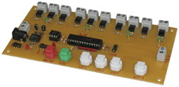
Programmable 4-Channel 10 Solid State Relay Controller |
Hardware Description | |||||||||
Board Size: |
This unique board was designed to allow you to control, record
and playback operation of 4 sets of solid state relays. Up to
45 minutes of relay activity can be recorded in non-volatile
memory. Recording is initiated and terminated by pressing the
Record Start/Stop pushbutton. Recording can be locked out by
switching the Program Lock switch. Playback of the sequence can
be initiated by pressing the Play button or by dry contact closure
at the Remote Trigger Terminal. The playback can be looped indefinitely
by switching the Loop switch. Power supply not included. |
|||||||||
|
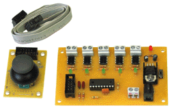
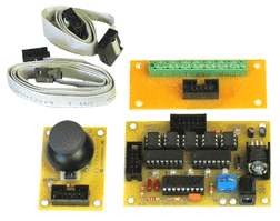
5-Ch Joystick to SS Relay Boards | Hardware Description | |||||||||
Joystick / Switch to 5-SS Relay Board Sizes: Joystick: 2-1/8" L x 1-1/2" W x 1-1/2" H Controller: 4" L x 2-1/2" W x 1/2" H Joystick / Switch to 5-SS Relays -Remote Connection Board Board Sizes: Joystick: 2-1/8" L x 1-1/2" W x 1-1/2" H Controller: 3-1/4" L x 2-1/4" W x 1/2" H Remote Board: 3" L x 1-1/4" W x 1/2" H |
4-Ch Joystick to 4-SS Relays and 1-Ch Joystick Switch to SS Relay These boards was designed to allow the control of 5 Solid State relays using a small joystick. The joystick is remotely connected to the main board via a 6 foot ribbon cable. Power is applied via a 2.1 mm barrel power connector or adjacent terminal block. A red LED on both the Main and Remote board indicates that power is applied to the board. The SS relays each have a green LED to indicate that they are activated. The joystick is configured to activate one of the 5 SSR's
when moved. Movement up will trigger SS Relay A, down, SS Relay
B, left SS Relay C and right, SS Relay D. There are two different board configurations available. Board
one has SS relays on-board and Board two has Remote connected
wire terminal board for connection to SS Relays Relays are rated 9-12 Vdc @ 2 Amp |
|||||||||
|
TTL - 1 Ch Relay Board | Hardware Description | |||||||||
Board Size: Approx: 2" L x 1" W x 5/8" H .Instruction Overview |
This board uses 1- bit ( TTL - level signal ) of digital output
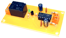
to control another device through an on board relay. |
|||||||||
|
TTL - 4 Ch Relay Board | Hardware Description | ||||||
Board Size: Approx: 2-1/4" L x 2-1/8" W x 1/2" H .Instruction Overview |
This board uses 4- bit ( TTL - level signal ) of digital output
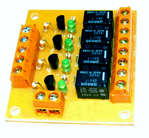
to control another devices through four on board relays. |
||||||
|
TTL -1 Ch Latching Relay Board |
Hardware Description | ||||||
Board Size: Approx: 2-3/8" L x 1-1/4" W x 1/2" H .Instruction Overview |
This board allows you to switch a relay ON and OFF as a latching
Normally Open (N.O.) to Normally Closed (N.C.) or vice-versa
state using only a single pulse from a TTL signal input. |
||||||
|
Sound Activated Solid State Relay Driver Board ( Solenoid / LED Driver) |
Hardware Description | ||||||
Board Size Approx: 3-1/4" L x 2-3/8" W x 3/4" H Relay = 1 Amp @ 60 VDC . Instruction Manual Application Examples: Pneumatic- Mouth Mechanism Water Valve- Dancing Fountain LED's - Dancing Lights DC Motor Driver- "Talking Fish" |
Board accepts audio input from any non-amplified sound source
(computer, CD player, or Digital Sound Board) and activates a
Solid State Relay ON and OFF in sync with the incoming audio
signal. The on-board 1 Amp Solid State Relay can be connected
to any device using (3-60 Vdc @ 1 Amp power). Common application
include driving a pneumatic solenoid valve, water valve to sound
or operating large bank of LED's -DC lighting to the incoming
sound. |
||||||
|
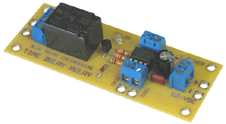
Time Delay Relay Board | Hardware Description | ||||||
Board Size: Approx: |
This board when triggered, will activate a relay for a specified
period of time. This time is controlled by a "timing resistor"
which is easily replaceable by the user. The trigger can be a
switch closure (supplied by User) , other relay, Wizard Board
REM port, or if you remove the "pull up resistor" the
board can be triggered by touching your finger to wires coming
from the trigger terminals. |
||||||
|
Interval Timer Relay Board |
Hardware Description | ||||||
Click on image for a closeup view Board Size: Approx: 3-5/8" L x 1-7/8" W x 7/8" H . Instruction Overview |
This board, when power is applied, will cycle ON and OFF a
10 amp relay. The relay on time and off time can be independently
controlled. The relay will continue cycling ON and OFF until
the power to the board is turned off. |
||||||
|
Sound Activated Delay Relay | Hardware Description | ||||||
Board Size Approx: 3-7/8" L x 2-5/8" W x 7/8" H .,,, Instruction Overview Resistor Time Chart |
(10 Amp Mechanical Relay) Board accepts audio input from any non-amplified sound source (computer, CD player, or Digital Sound Board) and when the volume reaches a certain level, it activates the on-board delay timer relay circuit on. The relay can be set to switch off after a delay time period. Sound Input: There is an on-board potentiometer that
is used to adjust the sensitivity to the incoming sound. The
board has a 1/8" phono jacks for input that can be switched
as a left or right audio input signal. An on board LED indicates
when the relay circuit is activated. |
||||||
|
Sound Activated Relay Module (10 Amp Mechanical Relay) |
Hardware Description | ||||||
Board Size Approx: 3-1/8" L x 2" W x 7/8" H ,,,Instruction Overview |
(10 Amp Mechanical Relay) Board accepts audio input from any non-amplified sound source
(computer, CD player, or Digital Sound Board) and when the volume
reaches a certain level, it activates an on board 10 Amp relay.
The relay can be used to switch another device on and off in
sync with the volume of the input. There is an on-board potentiometer
that is used to adjust the sensitivity to the incoming sound.
The board has a 1/8" phono jacks for input that can be switched
as a left or right audio input signal. An on board LED indicates
when the 10 Amp relay is activated. Relay has NO, Com, NC wire
terminal block contacts (form C relay). Board operates from 12
VDC power supply. |
||||||
|
8 - Ch Solid-State Relay Switching Controller (12VDC) |
Hardware Description | ||||||
Board Size: |
This single power board allows the individual control of 8
Solid State Relays by remote switches, relays or programmable
controllers and 12 VDC @ 2 Amp throughput power to the attached
devices. Specifications: Power supply , remote switches not included. |
||||||
|
1Ch To 4Ch Solid-State Switch Controller |
Hardware Description | ||||||
Controller switches 1 channel input out to 2 different Solid
State Sections |
|||||||
|
2 Ch Solid-State Relay Switch Controller |
Hardware Description | ||||||
Controller switches 2 channel inputs through controlled Solid
State Relays |
|||||||
|
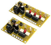
4Ch / 2Ch Solid-State Relay Switch Controllers |
Hardware Description | |||||||||
Click on image for a closeup view |
4 Channel Switcher - 1 channel input controls1-4 different
Solid State Relays. 2 Channel Switcher - 1 channel input controls 1-2 different
Solid State Relays |
|||||||||
|
Isolated DC Relay Boards Switching Relay Board A Power Switching Relay Board B |
Hardware Description | |||||||||
Switching or Power Switching Relays has isolation between
load and control inputs. Option Relay- A Option Relay- B |
||||||||||
|
10 Amp Solid State AC Relay Module |
Item Description | |||||||||
Click on image for larger view Board Size: 4" L x 2-1/2" W x 1-3/4" H .... .,,, Solid State Relay Setup Example |
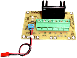
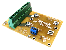
Relay Module This heavy duty SS Relay Module can be used to control ON and OFF any 50-240 VAC device up to 10 Amps from a small +5 Vdc control signal. +5 Vdc control signal can be sent from any of the Wizard,
Puppet controller boards Digital Output port to operate the SS
Relay module board, or any device that generates a +5 Vdc signal
can be used. |
|||||||||
|
Solid State AC Relay Modules |
Item Description | ||||||||||||
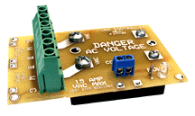
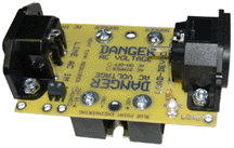
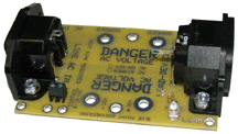
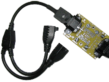
AC Voltage Warning Note ... Board Size: 4" L x 2-1/2" W x 1-3/4" H Solid State Dimmer Setup Example AC Voltage Warning Note |
These Heavy Duty SS Relay Modules can be used to control ON
and OFF any AC device from a small 5 -Vdc control signal. 5 -Vdc control signal can be sent from any of the Wizard,
Puppet controller boards Digital Output port to operate the SS
Relay module board. |
||||||||||||
|
Solid State Relay Module - AC Voltage - |
Item Description | |||||||||
Solid State Relay Setup Example AC Voltage Warning Note |
This compact SS Relay Module can be used to control ON and OFF any 20-140 AC voltage device up to 0.5 Amps from a small 5 Vdc input control signal. 5 Vdc control signal can be sent from any of the Wizard, Puppet
controller boards Digital Output port to operate the SS Relay
module board. |
|||||||||
|
Solid State AC Voltage Dimmer Module |
Item Description | ||||||||||||
Board Size: 4" L x 2-1/2" W x 1-3/4" H Solid State Relay Setup Example AC Voltage Warning Note |
The SS Dimmer Module can be used to dim up and down ( lighting ) any AC device 3-120 VAC up to 20 Amps from a simple 0-10 Vdc control input signal. 0-10 Vdc control input signal can be sent from Servo to Analog
converter board and any Wizard, Puppet Controller Boards servo
port to operate the SS Dimmer Module. |
||||||||||||
|
Solid State Relay Module -A
AC Voltage ON/OFFItem Description
Click on Images for a Closeup View
Board Size: with SS Module
3-7/8" L x 2-1/2" W x 2-1/8" H
SS Relay Module PCB Adapter
Board Size: without SS Module
3-7/8" L x 2-1/2" W x 1-3/8" H
Solid State Relay Setup Example -1
Solid State Relay Setup Example -2
WARNING:
This is a potentially dangerous
board as it connects directly
to live AC voltage. Only those
with a knowledge of how
AC Voltage works should use it.
Solid State ON / OFF Relay Module - A The Solid State Relay Module can be used to Switch On / Off AC device up to 10 Amps from a simple 0 -10 Vdc control signal.
0-10 Vdc control signal can be sent from Programmable Controller, Manual Adjustable Voltage supply, Servo to Analog converter board and any Wizard, or Puppet Controller Boards servo port to operate the SS Relay On / Off Module.
Module has LED Status indicator,
AC Power Plugs for quick connection.
0-2 Volts = Relay Off
3-10 Volts = Relay On ( Full )
AC Voltage loads = 10Amp
Wizard, Puppet boards, Programmable Voltage controller, Manual controller, AC power cords - not included.
NOTE:
SS Relay requires Heatsink for large AC loads - not included
Each Module requires AC Power IN cord and Output cord for operation
Solid State Relay with Power Cord ConnectionsAC WARNING
AC Voltage Warning NoteCustom Order, Please Contact Blue Point Engineering for Details
Product Description Catalog No. Price US $ Solid State Relay Module -A SDM-0010 $ 185.00 SS Relay Module PCB Adapter ( No SS Relay Module -A) SDM-0012 $ 80.00 AC Power IN Cord
... ( Required to connect module to wall AC outlet )ACP-0226 $ 17.85 AC Power Cord "Y " with Power outlets
... (Suggested for Each SS Power Module)ACP-0220 $ 23.50 Programmable Controller - 4 Channel ADB-6203 $ 365.00 AC Power Cord - Add on / Extensions
Solid State Module -B
AC Voltage DimmerItem Description
Click on Images for a Closeup View
Board Size: with SS Module
3-7/8" L x 2-1/2" W x 2-1/8" H
SS Dimmer Module PCB Adapter
Board Size: without SS Module
3-7/8" L x 2-1/2" W x 1-3/8" H
Power Cord Setup Example -1
Power Cord Setup Example -2
WARNING:
This is a potentially dangerous
board as it connects directly
to live AC voltage. Only those
with a knowledge of how
AC Voltage works should use it.
Solid State AC Dimmer Module - B The SS Dimmer Module can be used to dim up and down any AC device ( lighting ) up to 10 Amps from a simple 0 -10 Vdc control signal.
0-10 Vdc control signal can be sent from Programmable Controller, Manual Adjustable Voltage supply, Servo to Analog converter board and any Wizard, or Puppet Controller Boards servo port to operate the SS Dimmer Module.
Module has LED Status indicator,
AC Power Plugs for quick connection.
0 Volts = Dimmer Off
5 Volts = Dimmer 50 % On ( Half )
10 Volts = Dimmer 100 % On ( Full )
Voltage between 0 -10 variable power out.
Analog converter board Wizard, Puppet boards, Programmable Voltage controller, Manual controller, AC power cords - not included.
NOTE:
Dimmer Module requires Heatsink for large AC Dimming loads - not included
Each Module requires AC Power IN cord and Output cord for operation
Solid State Dimmer with Power Cord ConnectionsAC WARNING
AC Voltage Warning NoteCustom Order, Please Contact Blue Point Engineering for Details
Product Description Catalog No. Price US $ Solid State Dimmer Module -B SDM-0015 $ 365.00 SS Dimmer Module PCB Adapter ( No SS Dimmer Module) SDM-0019 $ 125.00 AC Power IN Cord
... ( Required to connect module to wall AC outlet )ACP-0226 $ 17.85 AC Power Cord "Y " with Power outlets
... (Suggested for Each SS Power Module)ACP-0220 $ 23.50 Programmable Controller - 4 Channel ADB-6203 $ 365.00 R/C Servo to Analog Converter PWC-2202 $ 75.00 AC Power Cord - Add on / Extensions
Relay - Manual Switch Controlled AC Power Switch 1-Ch Solid State Relay - 8 Amp |
Hardware Description | |||||||||
Click
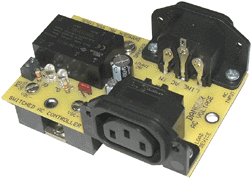
on image for a setup view Small Board Size: 4" L x 2-1/2" W x 2-2/4" H Power Cord Input Setup Power Cord Output Setup |
This special Solid State Relay Module can be used to Switch
On and Off AC powered device up to 8 Amps from a remote relay,
or manual operated switch . This board connects directly to live AC Voltage. |
|||||||||
|
Servo Controlled AC Power Switch 1-Ch Solid State Relay - 8 Amp |
Hardware Description | |||||||||||||||
Click
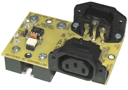
on image for a setup view Board Size: 4" L x 2-1/2" W x 2-2/4" H Power Cord Input Setup Power Cord Output Setup |
Solid State Relay AC Power Switch This special Solid State Relay Module can be used to Switch
On and Off AC powered device up to 8 Amps from any standard Servo
Controller. NOTE: This board connects directly to live AC Voltage. |
|||||||||||||||
|
AC Solid State Relay with
DC Power Output on board
AC and 5 / 9 VDC Power on boardHardware Description
Closeup View
Front View
Board Size:
4-3/8" L x 3-3/8" W x 1-1/8" H
Power Cord Input Setup
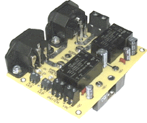
Power Cord Output SetupAC Solid State Relay Switch with DC Power on board This special self contained module can be used to Switch On and Off AC powered device up to 8 Amps from a remote relay or manual operated switch directly from the board. In addition there is also 9 VDC on board for powering other DC devices directly from the board. There are two on board AC to DC converters providing DC Voltage.
5 VDC voltage at 600 mA (Power for SS Relay module)
9 VDC voltage at 330mA output availableOn Board connection from remote switch / relay, power and relay status LED's.
NOTE:
Remote Relay or Manual Switch required for Control of AC Power Switch.
AC Power Cords, remote relay, switch, wires not included.
WARNING:
This board connects
directly to live AC Voltage.
Product Description Catalog No. Price US $ AC / DC Power Switch with Solid State Relay SDM-0116 $ 345.00 AC Power IN / Out Cords
.( Required to connect module to wall AC outlet and Load )- - To Top of Page
Remote Programmable 4 - Ch AC Voltage 15 Amp Solid State Relay Board |
Hardware Description | ||||||||||||
Click on Images for other Views |
Solid State AC Voltage Relay Board Description: |
||||||||||||
|
Micro Solid-State Relay Switch Modules |
Hardware Description | ||||||||||||
|
NEW DESIGN with 4-AMP Relay / LED Status Relay module has one Solid State Relay output with wire terminal
strips for quick device hookup. Relay acts as a switch. SS Relay
has isolation between load and control inputs, outputs, and load
pass through. Option SS Relay- A Option SS Relay- B Option SS Relay- C |
||||||||||||
|
Mini SS Relay Module | Hardware Description | ||||||
Relay Board Size: 1-5/8" L x 1-1/4" W x 3/4" H Relay rated for 60V DC at 1 Amp |
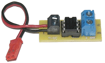
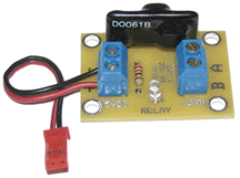
Relay module has one semiconductor type Solid State Relay
output with wire terminal strips for quick device hookup. |
||||||
|
Mini PIR Sensor Module | Item Description | ||||||
Click on image for a closeup view Board Size: 2" L x 1-3/8" W x 1/2" H Relay Rated: 12 Vdc at 1 Amp Requires 7-12 Vdc regulated power supply [ Application Examples ] |
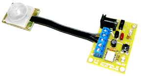
Small board, PIR sensor module with switching ON and OFF Solid
State relay, power connection, wire terminals for quick setup.
Board requires 7-9 Vdc regulated supply Power supply not included |
||||||
|
PIR Sensor Module | Item Description | ||||||
2-1/8" L x 1-3/4" W x 3/4" H Requires 9 Vdc regulated power supply Product Video |
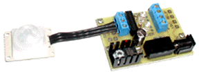
Complete PIR sensor module with switching relay, power connection,
wire terminals for quick setup. Small board size. Reed Relay Switching current 0.5Amp (Normal Open mode) 9 Vdc power supply not included |
||||||
|
Solid State Relay Switch Module | Item Description | |||||||||
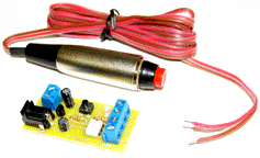
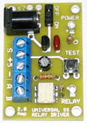
Click on image for a closeup view Board Size: 2-1/4" L x 1" W x 1/2" H Requires 7-9 Vdc regulated power supply [ Application Examples ] |
Universal board will switch Solid State 1 Amp Relay with input.
Input can be manual switch, relay, hand held wireless controller,
sensor or even other remote relay closure contact Board requires 7-9 Vdc regulated supply Power supply not included |
|||||||||
|
Universal Sensor Module | Item Description | ||||||
Click on image for a closeup view Board Size: 2" L x 1-3/8" W x 1/2" H Requires 7-12 Vdc regulated power supply [ Application Examples ] |
Universal sensor board will power any 5 vdc sensor with connection
for power, ground and sensor signal connection. Board requires 9 Vdc regulated supply Power supply, PIR Sensor not included |
||||||
|
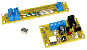
Latching Reed Switch Module | Item Description | ||||||
Relay Rated: 12 Vdc at 1 Amp |
New Design Coming Soon Currently Under Development |
||||||
|
Time Delay Power Relay Module | Item Description | ||||||
Board Size: 2" L x 12" W x 1/2" H |
Pre-programmed PIC power relay will activate solid state relays
after time period expires and pass connected voltage through
relays when time delay is over Board requires 7-24 Vdc supply Power supply not included |
||||||
|
R/C - 1 Ch Switch Board 10 Amp Solid State Relay |
Hardware Description | |||||||||
Board Size: 2-1/2" L x 2-1/8" W x 1" H Application and Setup Overview |
10 Amp Solid State Relay This board will take a RC Servo signal from any standard RC
transmitter and receiver or Wizard Servo board and toggle the
operation of a10 amp Solid State DC Relay. When there is no servo
signal being input, the relay will be off. When the servo signal
is about 1 mS then the relay will come on and will stay on until
the servo signal goes to about 2 mS and then the relay will go
off. The relay will then stay off until the servo signal goes
back to about 1 mS. (R/C transmnitter, receiver, Wizard servo board, power supply not included) |
|||||||||
|
Linear / DC Motor Module 12 VDC Control Activated Relay Module - 10 Amp |
Hardware Description | ||||||
Board Size: 4-1/4" L x 2-1/4" W x 1" H .Instruction Guide |
This unique board was designed to allow the directional control
of a 12V DC Linear (In / Out or standard CW / CCW) DC motor using
the presence (+on) or absence (0-off) of a 12V control signal
at the on-board Signal Input Terminal. When the signal is
present, the motor will run in one direction (motor dependent).
When the signal is not present, the motor will run in the opposite
direction. |
||||||
|
Switch Controlled Linear / DC Control Module Relay Module - 10 Amp |
Hardware Description | ||||||
|
Relay Control Module This unique board was designed to allow the directional control of a 12V DC Linear (In / Out or standard CW / CCW) DC motor by a dry contact closure ( Switch / remote relay) at either the on-board CW or CCW Switch Connector terminal block or by pressing the adjacent on-board pushbutton. When a signal (Switch / Relay closure) is present at either one of the control terminal blocks (or button), the motor will run in the associated direction (CW or CCW). When a signal is not present, the motor will not run. When the motor is moving in one direction, the other directional input is ignored until the current input signal is stopped. There are 2 limit switch inputs, one for each direction, that should be hooked to N.C. dry contact closure-type switches. When a limit switch is opened, it will stop or prevent movement in the associated direction the motor was operating such as in (CW / CCW, Linear Movement IN / Out) The on board electronics is powered from a DC source of 12-VDC, 100 mA minimum. Power to the board can be applied via the 2.1mm barrel-type connector or the adjacent 2-position terminal block and is indicated by a red LED. Power for the motor should be 12VDC at a current applicable (10 Amp max) for the motor attached. It is applied via the 2.1mm Motor Power connector or the adjacent 2-position terminal block, indicated by a red LED. A Tri-Color LED next to the Motor Output connector indicates that motor power is present and motor direction- Red / Green. Input LED's indicate which Directional Switch / Relay is active. Adjacent to the Aux Motor Power Terminal Block, there is a terminal block for the connection of a Emergency Stop Switch (Estop), (EPO Button).When this is activated all power to the motor is immediately stopped. An LED indicates if the EPO button is activated ON or OFF. Board Requires 2 power supplies, 1-for Board electronics,
1-for Motor power |
||||||
|