Welcome ...Product Categories ...What's New ...Sale Items ...Communications
E-Mail ...How to Order ...Order Form ...Catalog ...Legal Notices
. Control Boards / Devices: Analog-Digital Controller Products
.Back to Controller ListingWizard - 10 Control Board
8- Sounds FX to 1-8 Ch outputsWizard - 13 Control Board
Digital / Analog ControllerWizard - 15 Control Board
Input / Output I/O Router Controller0-10 Vdc Output Controller
0-10 Volts programmable outputPWM to Analog Converter
Servo PWM to 0-10 Vdc output5V Solid State Relay Control
5VDC +/- Control Duo Relays On / OffDigital SS Relay Controller
Programmable SS Relay Controller0-10 Vdc Analog Servo Control
0-10 Vdc Variable Input / 1- Ch Servo0-10 Vdc 6Amp HD Controller
0-10 Volts output High Current
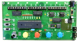
Wizard - 10 Board Sound & I/O Switchers |
Hardware Description | |||||||||||||||
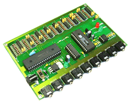
The other 8 banks of pin-sets along the back edge are for selecting which sound track goes to which output- jack matrix. ( remote amp and speaker ) Pin-set 1 (on the extreme left) relates to sound track 1- if you want sound track 1 to play-back through outputs 2, 6 and 8 you would put a jumper over pins 2, 6 and 8 on pin-set 1. If you want to play sound -track 2 through outputs
1,3 and 5 then you would put jumpers over pins 1, 3 and 5 on
pin-set 2 etc. |
Programmable board will switch 8 different digital recorded
audio signals to 1-8 different output channels. There is 1 audio jack input for recording 8 different sounds into the Digital sound chip directly by an audio source and 8 on board line output channels jacks to remote amps and speakers setups. There is the standard record/playback mode jumper selection along with led indicators. Board can even be set to play random or sequence sound playback when triggered You can adjust the play-back output select jumpers at any time- they are read just before starting any new play-back. When the audio is combined with any of the Wizard Relay boards,
the system becomes an automated audio sound effects and switcher
system. |
|||||||||||||||
|
Wizard - 13 Board Digital / Analog Board |
Hardware Description | |||||||||
Board Size: 167 x 86mm |
The Wizard 13 board provides up to 6 minutes of recording
and playback time for up to 6 digital outputs, 2 PWM and 4 DAC
outputs. Specifications: |
|||||||||
|
Wizard - 15 Board Input - Output I/O Router Board |
Hardware Description | |||||||||
Board Size: 100 x 150mm |
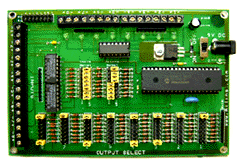
The Wizard 15 I/O router board provides a convenient way of matching up to 8 inputs with up to 8 outputs at 5V TTL levels. The board can accommodate normally high or low inputs and outputs and one single input may be routed to any or all of the output lines. A small led by each output indicates the current status. Specifications: |
|||||||||
|
0-10 VDC Input Signal To 1 Ch Servo Controller | Hardware Description | ||||||
2-7/8" L x 2" W x 1" H Assembled and Tested |
( Newly Enhanced ) This board uses a positive 0-10 Vdc signal to control the
position of a servo |
||||||
|
R/C Servo to Analog Converter Module |
Hardware Description | |||||||||
Small Board Size: 3-5/8" L x 1-1/4" W x 3/4" H Servo to Analog Board PWM to Analog Document |
This servo-analog converter board provides a two channel capability
of converting standard R/C servo PWM pulses to 0-10 Vdc and/or
0-5 Vdc outputs suitable for driving standard lighting dimmer
packs or any device that requires a 0-5 and/or 0-10 Vdc variable
controlled analog signal input. |
|||||||||
|
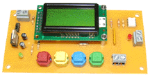
Digital Programmable Solid State Relay Controller |
Hardware Description | ||||||
Board Size: 4-3/4" Long x 2-3/8" Wide x 1" High Power Supply 7-24 V DC @ 100 mAmp Power Supply .. Board is pre-assembled and tested. Controller Instructions |
Digital Relay Board can be programmed with a Delay time, a
Relay On Time and a Loop function. All settings are stored in
non-volatile memory. There is a 4-Line by 16 Character back-lit
LCD that is the user interface for programming the different
modes of operation. These modes are set up and initiated using
a menu-driven display with input being made by on board pushbuttons. |
||||||
|
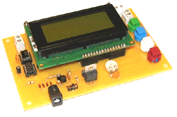
0-10 Vdc Output Programmable Controller Board |
Hardware Description | ||||||
Board Size: 5-1/4" Long x 3-1/2" Wide x 1" High Power Supply 7-24 V DC @ 100 mAmp Power Supply .. Board is pre-assembled and tested. Controller Instructions |
A unique 0-10 Vdc programmable output controller board allows
user to control DC voltage output in several different ways.
The output voltage is in 0.5V increments from 0 to 10V DC at
up to 25 mA. There is a 4-Line by 16 Character back-lit LCD that
is the user interface for programming the different modes of
operation. There are 8 modes of operation available to the user.
These modes are set up and initiated using a menu-driven display
with input being made by 4 on board pushbuttons. |
||||||
|
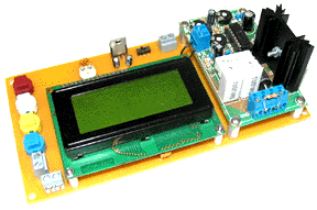
0 -10 VDC High Current Programmable Output Control Board |
Hardware Description | ||||||
Board Size: 6-3/4"" Long x 2-1/2" Wide x 2-1/4" High Power Supply 7-24 V DC @ 1 Amp Power Supply .. Board is pre-assembled and tested. Controller Instructions |
This board allows the user to control DC voltage output in
several different ways. The output voltage is in 0.5V increments
from 0 to 10V DC at up to 6Amp current. There is a 4-Line
by 16 Character back-lit LCD that is the user interface for programming
the different modes of operation. There are 8 Modes of operation |
||||||
|
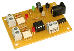
5Vdc +/- Input Control Duo Solid State Relay Interface Board |
Hardware Description | ||||||
Board Size: 2-1/2" L x 1-3/4" W x 1/2" H Application and Setup Overview |
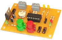
This board allows the control of two solid state relays with an incoming voltage signal that ranges from 5V to +5V DC. When the voltage signal drops below 2V DC, the left relay actuates and the Bicolor LED glows green. The relay will stay actuated as long as the voltage stays at or below 2V DC. When the voltage signal rises above 2V DC, Relay 1 will deactivate. When the voltage signal rises above +2V DC, Relay 2 will actuate and the bicolor LED will glow red. The relay will stay actuated as long as the voltage stays at or above +2V DC. When the voltage signal drops below +2V DC, Relay 2 will deactivate. When the voltage is between 2V and +2V DC, neither relay will be activated. The board requires a power source capable of delivering 7.5 to 24V DC which is connected to the board via a 2.1mm power connector. The power LED will illuminate when the power switch is turned on. |
||||||
|