Controller Menu

Welcome ...Product Categories ...What's New ...Sale Items ...Communications
E-Mail ...How to Order ...Order Form ...Catalog ...Legal Notices

Blue Line


Red Dot Icon . Control Boards / Devices: Motor Controller Products
Red Dot Icon .Back to Controller Listing
Servo Motor Controller Board
R/C Servo Motor - Direction / Speed
Programmable Motor Control
DC Motor Control with Limit Switches
Random Motor Controller
DC Motor On-Time Random
Programmable Linear Actuator
DC Motor Direction Control 8 Positions
R/C Motor Relay Controller
DC Motor Control by R/C Servo Ch
Linear Motor Controller
10 Amp DC Motor CW/CCW Control
Programmable Small Motor Control
4 Ch Motor Control with Limit Switches
Programmable Motor Control
DC Motor On-Off-Time / Direction
Joystick Motor Controller
8 Amp DC Motor CW/CCW Control
Programmable Timmed Motor
DC Motor On-Off-Time / Direction
Switch Controlled Motor Relay
10 Amp DC Motor CW/CCW Control
Linear Actuator Control
8 Amp DC Motor Direction Control
 Mini Joystick with Motor Logic
2-Channel Motor Direction Control
Programmable Linear Controller
5 Amp DC Linear Actuator Direction Control
DUO Program Motor Control
DC Motor On-Off-Time / Direction


Blue Line

To Top of Page

Motor Controller Hardware Description
motor control
Operating Instructions

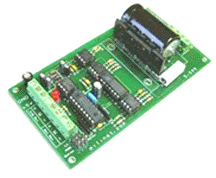
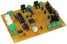
Motor Controller Board

Convert standard DC motors such as car windscreen motors into a powerful servo motor with this driver board.

Drive options include either standard R/C servo input signals (PWM 1-2msec pulse repeated every 20msecs) or 0 - 5V input.
Board may be configured for servo action or variable speed reversing DC motor drive.
Supports motors fron 9-24 Vdc up to 5A continuous current.

NOTE: Requires motor supply and 5V DC for the electronics (must be separate supplies or well isolated from each other)

NOTE: Some motors may have a hum when driven by the Motor Controller due to the design of the motor coil windings.

( power supply not included )
( DC motor, potentiometer, servo wires not included )

Size: 5-1/2" L x 2-5/8" W x 1" H

  Product Description
Catalog No.  Price US $
 Servo Motor Controller Board SBM-4500 $ 185.00

To Top of Page

Programmable DC Motor
Control Module - 10 Amp
Hardware Description

Programmable Motor Controller

Board Size:
6-1/4" L x 3-7/8" W x 1-1/4" H

Motor Relay rated at 10 Amps DC

Duo Power Supplies Required
Board Electronics 9-12 VDC
Motor Power 5- 24 VDC

Application Setup Overview


Programmable Motor Control Module

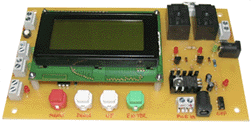
This unique board will allow the intermittent directional control (CW/CCW) of a DC motor. The time that the motor will travel in each direction is programmed into the board and is stored in non-volatile memory. There are limit switches that, when activated, will stop the motor.

The board can be triggered by either a dry contact closure at the Remote Trigger Terminal or by pressing the adjacent tactile switch. Once triggered, the motor will travel in the first direction for the programmed time, wait for a programmed time, travel in the opposite direction for a programmed time, wait for another programmed time and then the board will wait for the next trigger event. Alternatively, if Auto Loop is programmed to be on, the board will then wait for a programmed amount of time and then automatically repeat the entire process.
All programmed times can range from 1 second to 60 minutes. Programming is accomplished via a 4-line x 16 char LCD display and 4 programming buttons.

Power to the board is via a 2.1mm barrel-type connector or via the adjacent terminal block. Power to the motor is applied via another 2.1mm barrel-type connector or via the adjacent terminal block. LEDs on the board will indicate that power is present. There is a small slide switch at the top of the board that will allow you to turn on and off the LCD backlight. LEDs next to each limit switch terminal block will indicate that a limit switch is in the open condition. There is also a SS Relay contact that will close for 2 seconds at the beginning of motor travel in each direction. A LED next to the SSR Contact terminal block will indicate that the relay is active and the contacts are closed.

( Motors , Power supplies, limit switches - Not included )

  Product Description
Catalog No.  Price US $
Programmable DC Motor Controller - 10 Amp PMC-5600 $ 295.00
Custom Order, Please Contact Blue Point Engineering for Details

To Top of Page

Random DC Motor
Control Module - 10 Amp
Hardware Description
Motor Control Random
Board Size:
3-1/8" L x 3" W x 7/8" H

Motor Relay rated at 10 Amps DC
Duo Power Supplies Required
Board Electronics 9-12 VDC
Motor Power 5- 24 VD

Application Setup Overview

Random Motor Control Module

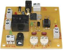
This board was designed to allow the operation of a DC motor ON and OFF for random time periods limited by on-board user set potentiometers

A connection for an E-Stop Switch (NC contact) is provided to stop motor travel when pressed. An adjacent LED will light when the E-Stop switch is activated. Also, a connection is provided for a Remote On/Off switch.

Power to the board is attached via a 2.1 mm barrel-type connector or the adjacent terminal block. Power for the motor is provided by a separate 2.1 mm barrel-type connector or adjacent terminal block.

Two on-board potentiometers are provided to set the maximum motor travel time and the maximum motor interval wait period. These times can be set from 1 second to 5 minutes.

( Motors , Power supplies, limit switches - Not included )

  Product Description
Catalog No.  Price US $
Random DC Motor Controller - 10 Amp PMC-1500 $ 165.00
Custom Order, Please Contact Blue Point Engineering for Details

To Top of Page

Programmable - 2 Ch Relays
with Relay Output Options
( DC Motor Timed Control )
Hardware Description


Board Size: Aprox
5-7/8" L x 3-5/8" W x 1" H

Relays Rated: 10 Amp

Board Power Supply
9-12 V DC @ 1 Amp


Programmable 2-Channel Relay Board
with relay output options.

Description:
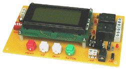
This board is designed to allow the timed-control of two 10A relays in several fashions. Timing is entered via menu-driven LCD and stored in non-volatile memory. Operational modes are set using a 4-position DIP switch. Relays have LEDs to indicate activity. Board can be triggered by dry contact closure at the Remote Trigger terminal block or by pressing the small tactile switch adjacent to it. The LCD is a 4-line x 16 character display that will prompt for user input or display event timing and relay status. A small switch at the upper right corner of the board turns on and off the backlighting for the LCD.

Mode Descriptions:
Modes of operation are controlled by the 4 position DIP switch on the left side of the board. These switches tell the board how it will operate.

The time limits for the Event Time is 1 second to 8 hours and for the Relay On Time, it is 1 second to 30 minutes

Board can be triggered by dry contact closure at the Remote Trigger terminal block or by pressing the small tactile switch adjacent to it. The LCD is a 4-line x 16 character display that will prompt for user input or display event timing and relay status. A small switch at the upper right corner of the board turns on and off the backlighting for the LCD.

Program Relay Modes:
(Count Up / Down- trigger)
(Auto / manual remote trigger)
(Relay Normal / Relays 1, 2 Flip-Flop)
(Relay On / Off at Start)
Power Supply- 9-12 V DC @ 1 Amp

Power supply, remote devices, connection wire, switch not included.

  Product Description
Catalog No.  Price US $
Programmable 2-Ch Relay Board DRB-0783 $ 295.00
Custom Order, Please Contact Blue Point Engineering for Details

To Top of Page

 Programmable
DC Motor Controller
Hardware Description
DC motor controller
Board Size: 4" L x 13-3/4" x 1" H
Application and Connection Setup Overview

Programmable DC Motor Controller

This board allows the control and recording of the CW / CCW movement of a DC motor. The motor can draw up to 5 Amps continuous.
Up to 12 minutes of motor movement can be recorded and stored on the on-board EEPROM and playback A Loop function is provided to allow the continuous replay of the recorded movement with a delay between replays from 1 second to 5 minutes.
Inputs are provided for limit switches with indicator LEDs that light when the associated limit switch has been activated. Replay can be triggered by pressing the Start/Stop button or remotely via dry contact closure. When playback is started, a 50 mS pulse is present at the Sync Output terminal block that can be used to trigger other boards. The board requires a 7.5 to 24 Vdc 100 mA power supply. A separate power supply is required to provide power to the motor being used and should be appropriately sized.

( Power supply, motor, and switches not included )

  Product Description
Catalog No.  Price US $
Programmable DC Motor Controller PMC-0655 $ 295.00
Custom Order, Please Contact Blue Point Engineering for Details

To Top of Page

 Programmable - 4 Channel
DC Small Motor Controller
Hardware Description


Board Size: 6" L x 5-5/8" x 1" H

Motor power can be 1V to 6VDC
Motors should not draw more than 100 mA

Application and Connection Setup Overview

Required Power Supplies
9Vdc Power Supply -Controller
1-6Vdc Power Supply - DC Motors

NOTE: Attached Motors can not
draw more than 100 mA each

Programmable DC Motor Controller

This board will allow the programming and recording movements CW / CCW /  STOP for 4 small DC motors and the actuation of a small solid state relay.

Features of this board include:
Limit Switch inputs for CW and CCW limits for each motor
LED indicators for motor direction
Separate power entry (2.1 mm barrel connector and 2-position terminal block) for motors with a switch and LED indicator
Remote switch capability for motor power
Separate power entry (2.1 mm barrel connector and 2-position terminal block) for controller board with a switch and LED indicator
Remote switch capability for board power
Pushbuttons for programming motor movement and relay actuation
Autostart feature to initiate playback upon power up
Programming lockout switch to prevent accidental overwriting
Non-volatile program storage- EEPROM on-board
Loop Switch for repeating playback automatically
Delay Pot to set a time (up to 5 minutes) to wait before repeating program (if Loop Switch is on)
Remote Trigger (dry contact closure) terminal block
Play and Record LED indicators
SS Relay test button and LED indicator
80 mS Synch signal at the start of each playback
Control Board requires 7.5 to 9VDC
Solid State Relay rated at 2 Amps

Motor power can be 1VDC to 6VDC
Motors can not draw more than 100 mA each


( Power supplies, motors, and switches not included )

  Product Description
Catalog No.  Price US $
Programmable DC Small Motor Controller PMC-0755 $ 295.00
DC Motors
Mini Motors / Gear Kits
   
Custom Order, Please Contact Blue Point Engineering for Details

To Top of Page

Linear Actuator / DC Motor
Controller by R/C Interface
Hardware Description


Board Size:
3-7/8" L x 2-5/8" W x 3/4" H

Operating Instructions

R/C Interface for Linear Actuator / DC Motor Control
New Design

This unique board was designed to allow the directional control of a Linear Actuator (IN / OUT) or DC Motor Rotation (CW / CCW) by using a R/C servo output channel (PWM Signal) to control the DC Motor movements / positions.

Two modes of operation are provided and are selected by the on board Mode Jumper. Toggle On and Off and Latching On and Off Control. On board limit switch inputs stop actuator if positions are exceeded.

The board is powered by the R/C servo connection, but separate power of 12 Vdc @ 5+ Amps must be provided for the linear actuator or DC motor. A power jack or wire terminal is on-board for easy connection to linear actuator motor power. A wire terminal block is also on-board for quick connection to the linear actuator motor wires
There are 2 on-board 6-Amp mechanical relays that work in conjunction to reverse the polarity of the power being supplied to the linear actuator motor that is attached at the motor connection terminal block by PWM (Radio Control) signals.

The board takes standard R/C servo inputs.
The linear actuator controller can also be connected to any of the Wizard Boards or Puppet Controllers for a fully programmable Linear Actuator Controller.

Controller has on-board PIC Microprocessor for R/C to Relay Control. 3-Pin header for quick servo wire connection from R/C receiver or Wizard board.
Tri-Color LED for Motor Rotation / Linear Position Status.

( Linear Actuator, Power supply - R/C System, Wizard Boards Not included )

  Product Description
Catalog No.  Price US $
R/C Linear Actuator Mechanical Relay Module - 6 Amp RCR-8600 $ 195.00
DC Linear Actuators- Assorted Sizes

LAM-0010

-
Programmable Wizard Boards

 -

 -
Custom Order, Please Contact Blue Point Engineering for Details

To Top of Page

Linear / DC Motor Module
12 VDC Control Activated
Relay Module - 10 Amp
Hardware Description

Motor control board

Board Size:
4-1/4" L x 2-1/4" W x 1" H

Instruction Guide

12 VDC Linear / DC Motor Relay Control Module

This unique board was designed to allow the directional control of a 12V DC Linear (In / Out or standard CW / CCW) DC motor using the presence (+on) or absence (0-off) of a 12V control signal at the on-board Signal Input Terminal. When the signal is present, the motor will run in one direction (motor dependent). When the signal is not present, the motor will run in the opposite direction.

There are 2 limit switch inputs, controlled by the on-board PIC microprocessor, one for each direction that should be hooked to N.O. dry contact closure-type switches. When a limit switch is closed, it will stop or prevent movement in the associated direction. The board can be powered from a DC source of 7.5V ­ 24V DC, 100 mA minimum. Power to the board can be applied via the 2.1mm barrel-type connector or the adjacent 2-position terminal block and is indicated by a green LED. Power for the motor should be 12VDC at a current applicable for the motor attached. It is applied via the 2.1mm Motor Power connector or the adjacent 2-position terminal block. A green LED next to the Motor Power connector indicates that motor power is present.
Relays rated for 10 Amp DC Voltage

Board Requires 2 power supplies, 1-for board electronics, 1-for motor power
( Motor , Power supplies, Switches - Not included )

  Product Description
Catalog No.  Price US $
12-VDC Control Motor Relay Module - 10 Amp MCR-4600 $ 175.00
Custom Order, Please Contact Blue Point Engineering for Details

To Top of Page

Switch Controlled
Linear / DC Control Module
Relay Module - 10 Amp
Hardware Description


Board Size:
4-3/4" L x 2-1/4" W x 1" H

Instruction Guide

Switch Controlled Linear / DC Motor
Relay Control Module

This unique board was designed to allow the directional control of a 12V DC Linear (In / Out or standard CW / CCW) DC motor by a dry contact closure( Switch / remote relay) at either the on-board CW or CCW Switch Connector terminal block or by pressing the adjacent on-board pushbutton.

When a signal (Switch / Relay closure) is present at either one of the control terminal blocks (or button), the motor will run in the associated direction (CW or CCW). When a signal is not present, the motor will not run. When the motor is moving in one direction, the other directional input is ignored until the current input signal is stopped. There are 2 limit switch inputs, one for each direction, that should be hooked to N.C. dry contact closure-type switches. When a limit switch is opened, it will stop or prevent movement in the associated direction. (CW / CCW, Linear Movement IN / Out)

The board electronics is powered from a DC source of 12-VDC, 100 mA minimum. Power to the board can be applied via the 2.1mm barrel-type connector or the adjacent 2-position terminal block and is indicated by a red LED. Power for the motor should be 12VDC at a current applicable (10 Amp max) for the motor attached. It is applied via the 2.1mm Motor Power connector or the adjacent 2-position terminal block. A red LED next to the Motor Power connector indicates that motor power is present.

Adjacent to the Aux Motor Power Terminal Block, there is a terminal block for the connection of a Emergency Stop Switch (Estop, EPO Button).When this is activated all power to the motor is immediately stopped.

( Motor , Power supplies, Switches - Not included )

  Product Description
Catalog No.  Price US $
Switch Controlled DC Motor Relay Module - 10 Amp MCR-4800 Not Available
New Design
Coming Soon
Custom Order, Please Contact Blue Point Engineering for Details

To Top of Page

Mini Joystick Module
with Motor CW / CCW Control
Item Description
Joystick
Click on Image for a view of Joystick Module

View of Joystick in User Hand

Setup Example

Mini Joystick with Motor
CW / CCW Control Setup

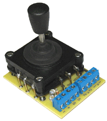
Unique 2 channel Joystick will control 2 small DC motors attached to the wire terminal blocks in CW (Clockwise) and CCW (counterclockwise) motor ration as the joystick is moved.
Two axis joystick (Switch) ( X-Y )

Easy Setup Connections: Attach motors, a power supply 3-12 Vdc to the wire terminal blocks and a remote On and Off power switch and your ready to control the two motor rotations from the joystick.

Joystick Size: - Data on Joystick
Approx: 2-1/2"H x 1-3/4" W x 1-3/4" W

Joystick PCB board Size:
2-5/8" L x 2" W x 2-3/4" H (Joystick Included)

Joystick module can be mounted in user optional enclosure box

Application Example

  Product Description
 Catalog No.  Price US $
 CW / CCW Motor Mini Joystick Controller JMM-0613 $ 195.95
 Basic - Mini Joystick Only

PJS-0610
 
Custom Order, Please Contact Blue Point Engineering for Details
OUT OF STOCK

To Top of Page

Mini Joystick Motor
Control Module
Item Description
motor joystick controller
Click on Image for a closeup view

Setup Example

Joystick with Motor
CW / CCW Control Board

DC Motor Control
Linear Actuator Joystick Control

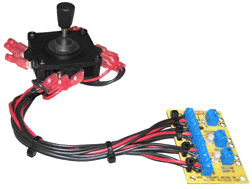
Unique 2 channel Joystick will control 2 DC motors attached to the wire terminal blocks in CW (Clockwise) and CCW (counterclockwise) motor ration as the joystick is moved.
Two axis joystick (Switch) ( X-Y )

Easy Setup Connections: Attach motors, a power supply 1-12 Vdc to the wire terminal blocks and a remote On and Off power switch and your ready to control the two motor rotations from the joystick and connected motor logic board.

Joystick Size: - Data on Joystick
Approx: 3"H x 4" W x 4" W with wire connectors

Motor Connection PCB board Size:
3" L x 3" W x 5/8" H

Lead wire connection between Joystick and Motor Logic Board.
Quick Wire connectors, color coded connection wires.

Joystick module can be easily mounted in an optional enclosure box

Application Example

  Product Description
 Catalog No.  Price US $
 Joystick Motor Controller 5 Amp JMM-0894 $ 195.95
Custom Order, Please Contact Blue Point Engineering for Details

To Top of Page

8 Position Programmable Linear
Actuator Control Module
Hardware Description
Programmable Linear Control

Board Size:
6-1/4" L x 3-3/4" W x 1-1/4" H

Motor Relay rated at 10 Amps DC

Duo Power Supplies Required
Board Electronics 9 VDC at 800 mAmp
Motor Power 12 VDC at 5 Amp

Application Setup Overview

8- Position Linear Actuator Control Module

This board was designed to allow the user to program the position of a VDC linear actuator. Eight positions can be programmed in with a wait time at each position that can range from 1 second to 5 minutes. The 8 positions can be selected at any length along the full travel.

Connections for a Home switch, Limit switches and an Estop button are provided with an associated LED that indicates when the switch is activated. After programming the eight positions, playback can be started by pressing the Enter button. Programming options include returning the actuator to Home position prior to starting playback and putting the board in Loop mode where the playback repeats over and over until stopped by pressing the Menu Button or hitting the Estop switch.

Power to the actuator is separate from the board power and is attached to the board via a 2.1mm barrel-type connector or the adjacent terminal block located at the top left of the board. Power for the board is also provided via a 2.1mm barrel-type connector or adjacent terminal block located at the bottom left of the board. A red/green bicolor LED will indicate which direction the actuator is moving

( Motors , Duo Power supplies, limit switches - Not included )

  Product Description
Catalog No.  Price US $
8-Position Programmable DC Motor Controller - 10 Amp PMC-5600 $ 295.00
DC Linear Actuators    
Custom Order, Please Contact Blue Point Engineering for Details

To Top of Page

Duo Programmable Linear Actuator
Control Module
Hardware Description
Programmable Linear Control

Board Size:
6-1/4" L x 3-3/4" W x 1-1/4" H

Motor Relay rated at 10 Amps DC

Duo Power Supplies Required
Board Electronics 9 VDC at 800 mAmp
Motor Power 12 VDC at 5 Amp

Application Setup Overview

Duo Programmable Linear Actuator Control Module

This board was designed to allow the user to program the position of a large linear actuator using one of 2 operational modes. One mode will allow you to program in 8 positions along the length of travel with a wait time of up to 5 minutes between each position. The other mode will allow the continuous recording of position for up to 8000 positions with an optional loop repeat delay of up to 5 minutes before replaying.

The current operational mode will be displayed when the board is first powered up. If you wish to change the mode, turn off the board, hold down the Menu button, turn the board back on (still holding down the Menu button) and the display will show that the new mode has been selected. The current mode will remain in effect until this procedure is repeated again.

Connections for a Home switch, Limit switches and an EStop button are provided with an associated LED that indicates when the switch is activated.

Power to the actuator is separate from the board power and is attached to the board via a 2.1mm barrel-type connector or the adjacent terminal block located at the top left of the board. Power for the board is also provided via a 2.1mm barrel-type connector or adjacent terminal block located at the bottom left of the board.

A red/green bicolor LED will indicate which direction the actuator is moving.

( Motors , Duo Power supplies, limit switches - Not included )

  Product Description
Catalog No.  Price US $
Duo Programmable DC Motor Controller - 10 Amp PMC-6000 $ 325.00
DC Linear Actuators    
Custom Order, Please Contact Blue Point Engineering for Details

To Top of Page

Programmable DC Motor
or
Linear Actuator Controller
Hardware Description
linear actuator control
Board Size:
4-1/4" L x 3-1/4" W x 1" H

Motor Driver rated at 5 Amps DC

Duo Power Supplies Required
Board Electronics 9 VDC at 800 mAmp
Motor Power 12 VDC at 5 Amp

Application Setup Overview

Programmable DC Motor Controller

This board was designed to allow the recording and playback of the movement of a linear actuator or rotational directional control of other DC motors that have a potentiometer-based position sensor.

The board can control an actuator that requires power of up to 24VDC at 5A. Power for the actuator can be supplied via power connectors separate from the board power (recommended) or, if the actuator does not require a lot of current, the board and actuator can be powered from the same power supply by shorting the Power Jumper Header. The Power LEDs will indicate that power is present.

There are terminal block connectors for limit switches and remote programming / control switch connections. The board also has a Loop Delay Pot that when used will cause the board to continuously loop the playback with a delay in between of up to 10 minutes.

The on-board EEPROM can store up to 8000 motion positions.

( Linear Actuator, Motors , Duo Power supplies, limit switches - Not included )

  Product Description
Catalog No.  Price US $
Programmable DC Motor Controller - 5 Amp PMC-5095 $ 195.00
DC Linear Actuators    
Custom Order, Please Contact Blue Point Engineering for Details


To Top of Page

To Top of Page ...Back to All Controller Listing ... Product Categories

Copyright © 2013 Blue Point Engineering LLC., All Rights Reserved

Blue Point Engineering LLC. (303) 651-3794

Blue Line